fordmano
Member

Posts: 1457
San Jose, CA. 1999 I/S 232 miles when bought 11/05
San Jose, CA.
|
 |
« Reply #120 on: February 03, 2011, 09:00:13 PM » |
|
I was able to get my Stebel horn cleaned up/spruced up a bit and remounted even cleaned up the mounting bracket I had made when I originally installed it,, the mount was a hack job and I was in a hurry so it is what it is. Here is how the mount and the horn looked like when I started out this morning.  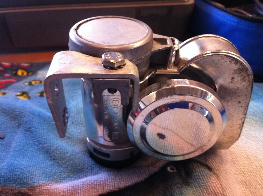 And with the help of my trusty dremel tool set and a little can of Spray paint it cleand up ok in my eyes. NO it does not come out Like Chrome, more like a semi polished Aluminum, but it is cheap and easy and is WAY better looking than chips and the undercoat black plastic showing in sparse places. 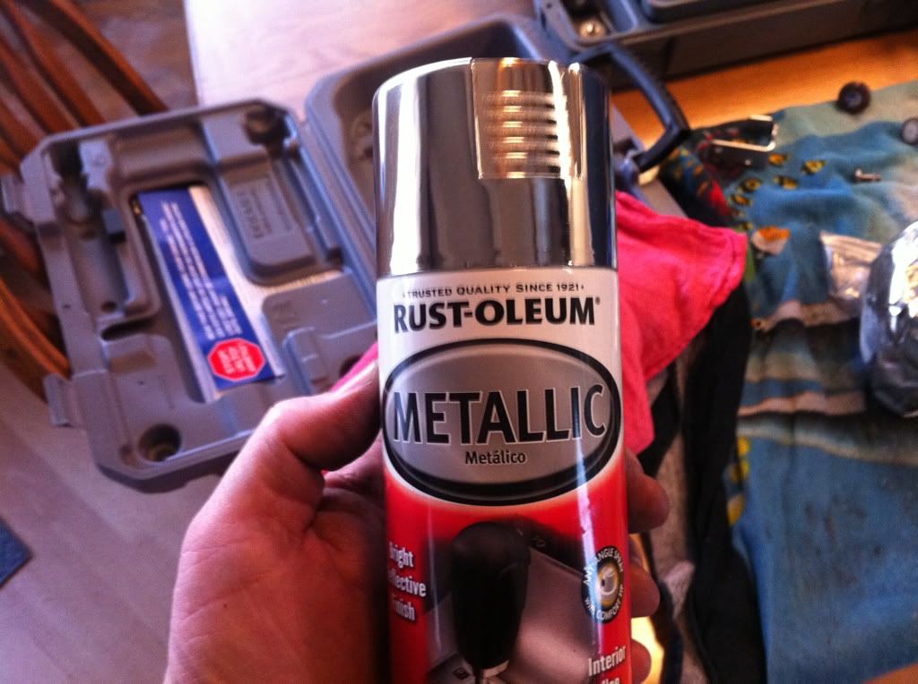 And here is the finished product. 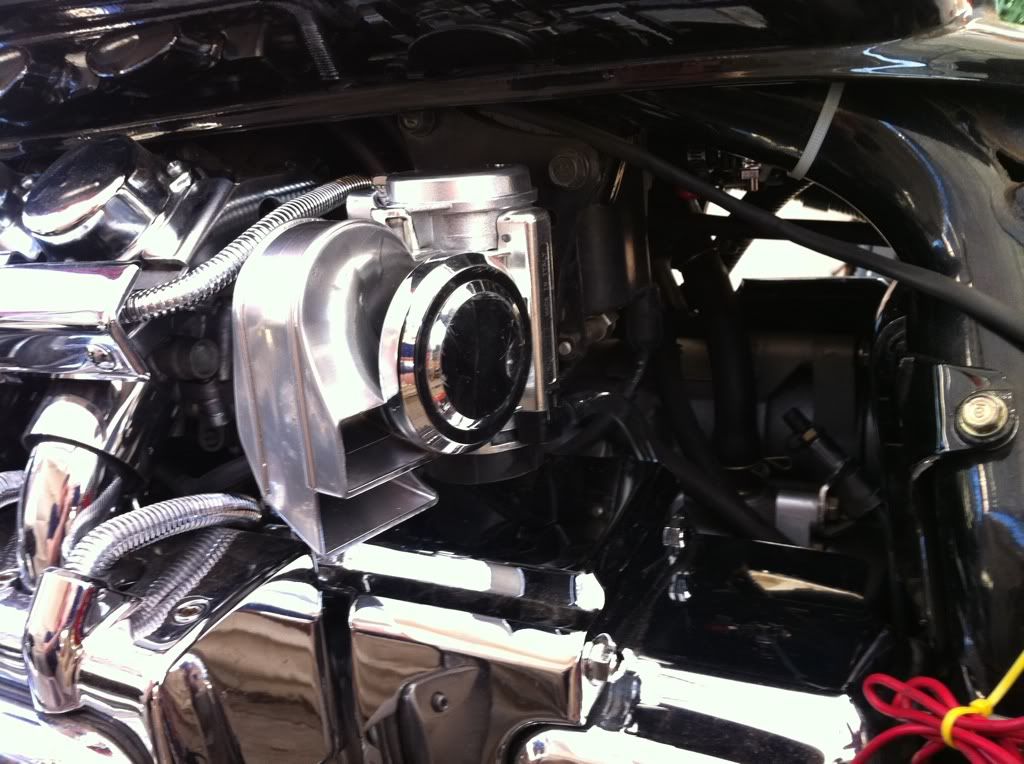 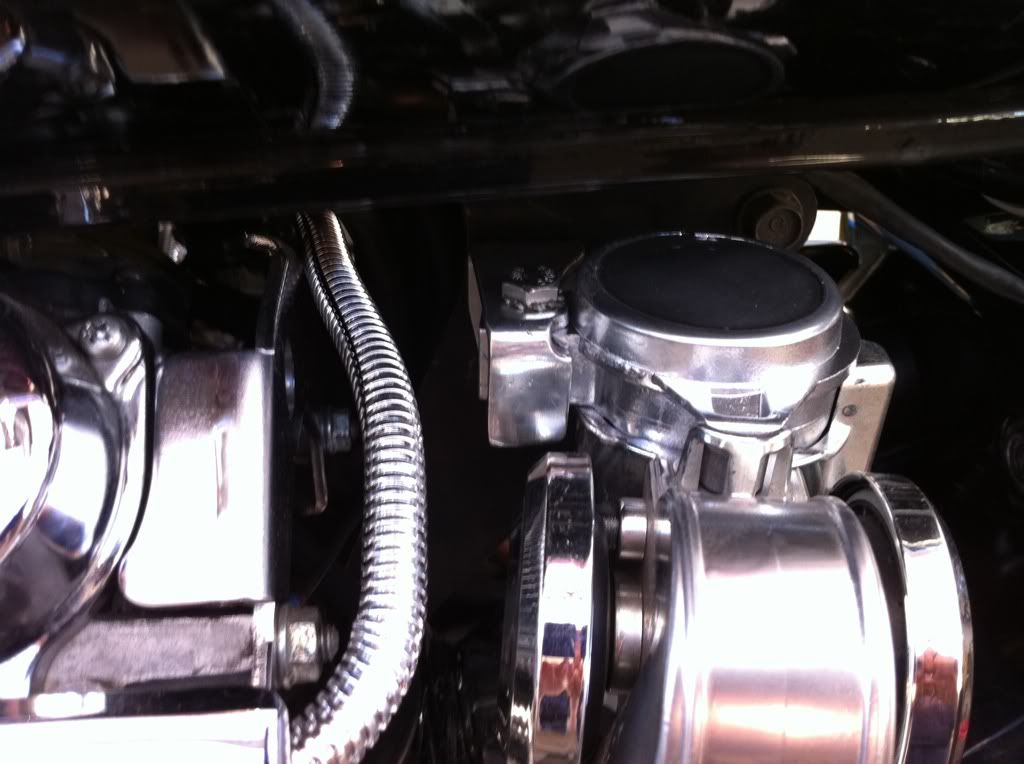 |
|
|
|
« Last Edit: February 03, 2011, 09:05:25 PM by fordmano »
|
 Logged
|
  83GS550 93XR650L TARD! 97WR250 99ValkyrieI/S Tri-tone 01YZ125(x2) 05DRZ-125 |
|
|
fordmano
Member
Posts: 1457
San Jose, CA. 1999 I/S 232 miles when bought 11/05
San Jose, CA.
|
|
« Reply #121 on: February 09, 2011, 01:59:20 AM » |
|
Time for another update,, really trying to focus on the AudioVox Cruise control install for the moment. So with that said, after looking at a few pictures of what others have to attach the actual cable and route it under and through the carburator bank. The 2 that I have seen that seemed the easiest (not many have shown any pictures of how to create the mount or even how to attach it). One is to use an "L" bracket and cut it up the other is to use a lentgh of steel strap and attach it to the top motormount. I used a piece of the mounting hardware that came with the Cruise Control kit. Of course I had to manipulate it a little bit. 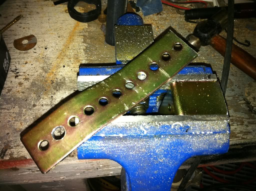 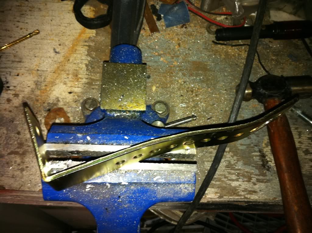 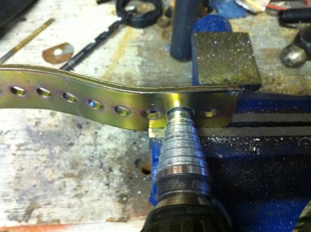 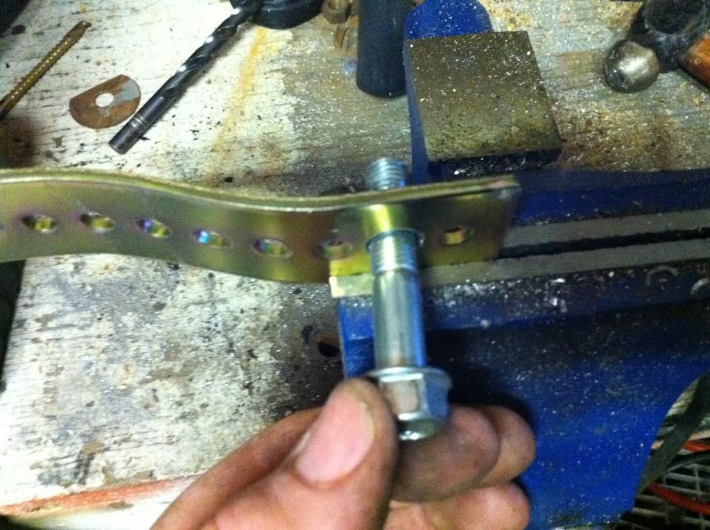 Getting the correct bend in it was probably the trickiest part after finally deciding what to use. 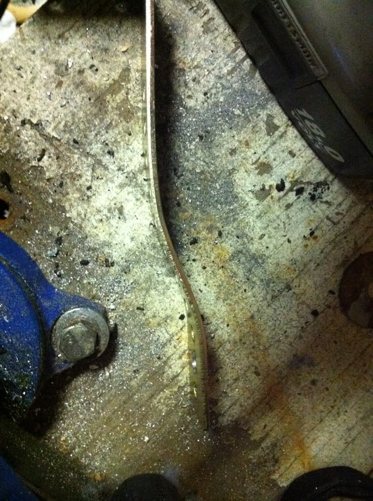 |
|
|
|
« Last Edit: February 09, 2011, 02:44:35 AM by fordmano »
|
Logged
|
83GS550 93XR650L TARD! 97WR250 99ValkyrieI/S Tri-tone 01YZ125(x2) 05DRZ-125
|
|
|
fordmano
Member
Posts: 1457
San Jose, CA. 1999 I/S 232 miles when bought 11/05
San Jose, CA.
|
|
« Reply #122 on: February 09, 2011, 02:08:28 AM » |
|
So here is the mount location, and of course doing it this way caused another little issue I had to work around. The Smog tubes had all been left in place when I did the de-smog and now this one is in the way. So I will come back to the smaog tube remove in a bit, a true Valk Lover will enjoy my fix for this removal.. 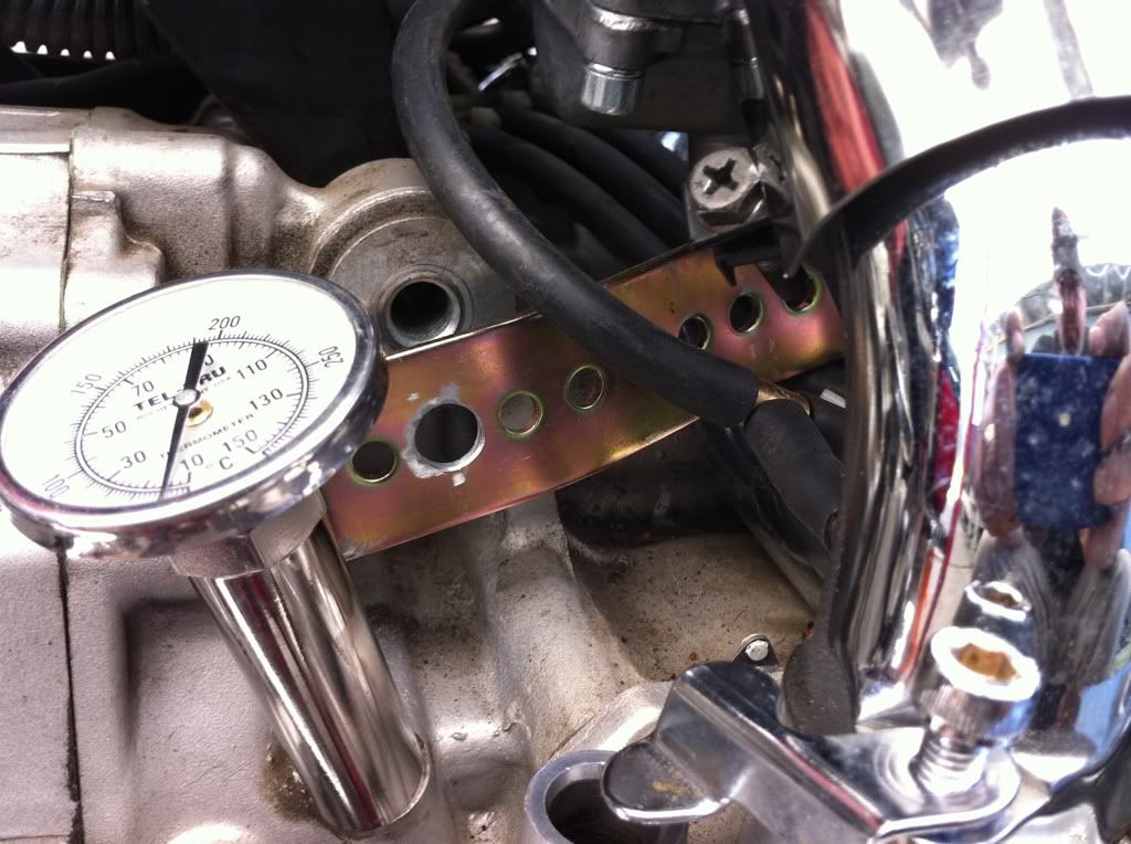 So adding this 1/8" thick strap ended up running me out of threads on the original bolt so I had to go find a replacement. 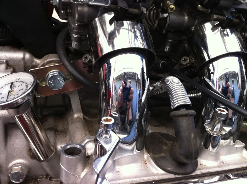 Figured I would show 2 views for clearity. 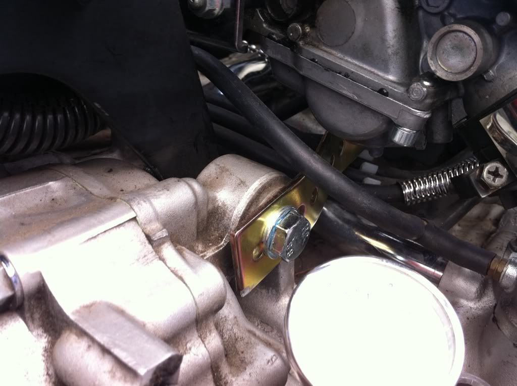 Now here is the cable mounting. 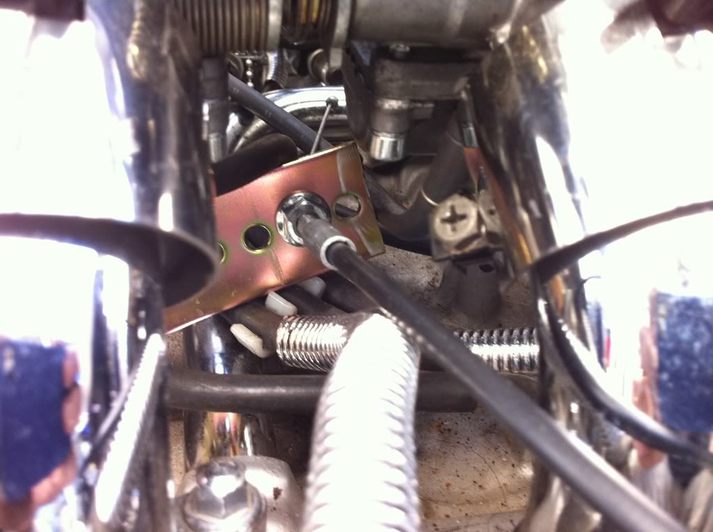 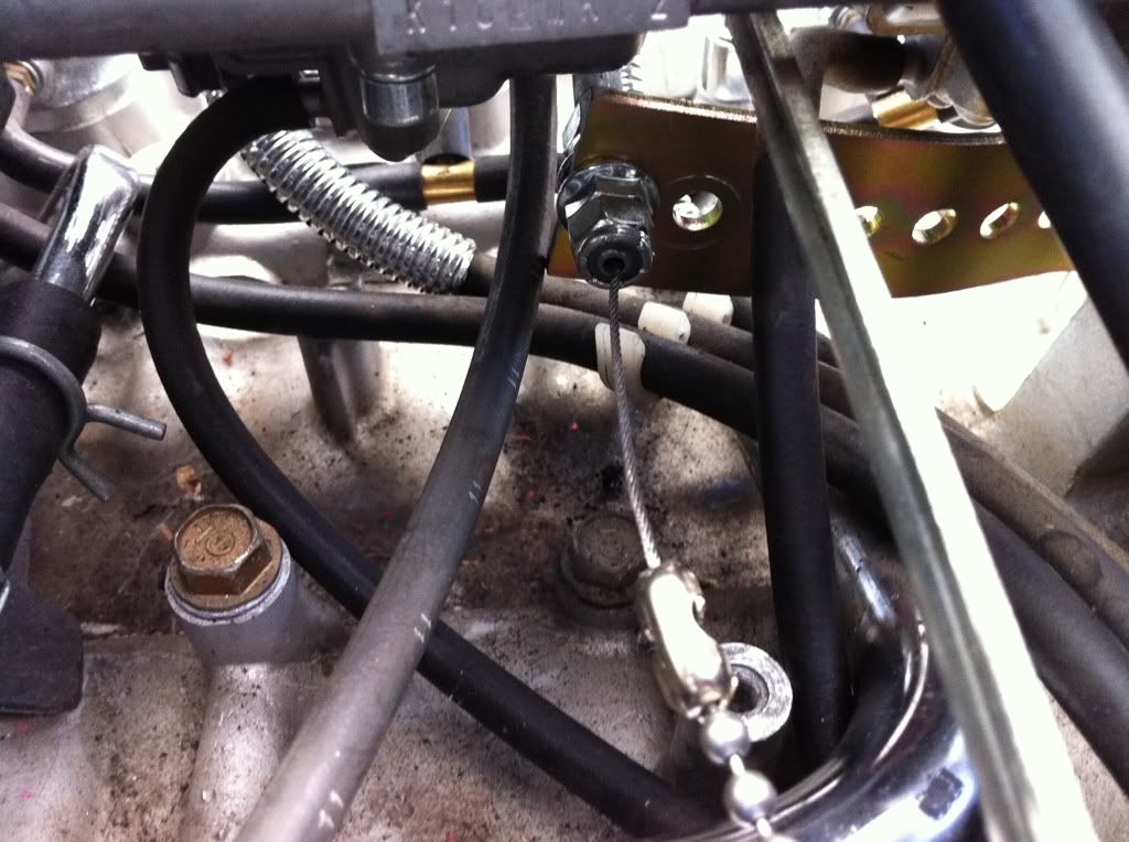 |
|
|
|
« Last Edit: February 09, 2011, 02:46:00 AM by fordmano »
|
Logged
|
83GS550 93XR650L TARD! 97WR250 99ValkyrieI/S Tri-tone 01YZ125(x2) 05DRZ-125
|
|
|
fordmano
Member
Posts: 1457
San Jose, CA. 1999 I/S 232 miles when bought 11/05
San Jose, CA.
|
|
« Reply #123 on: February 09, 2011, 02:12:22 AM » |
|
Ok just one more of the Cable mount, then the smog tube removal. 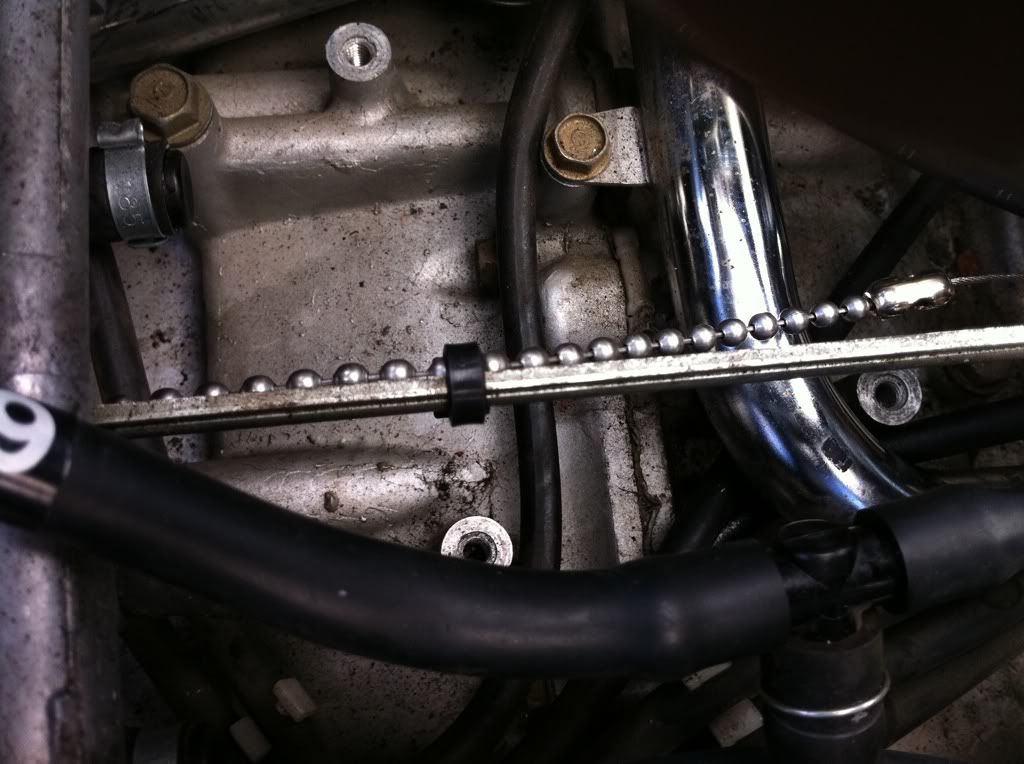 Yes I know so what, well the instructions I have seen reccomends to attach a tiestrap (zip tie) to keep the chain from hanging up on anything. |
|
|
|
« Last Edit: February 09, 2011, 02:47:16 AM by fordmano »
|
Logged
|
83GS550 93XR650L TARD! 97WR250 99ValkyrieI/S Tri-tone 01YZ125(x2) 05DRZ-125
|
|
|
fordmano
Member
Posts: 1457
San Jose, CA. 1999 I/S 232 miles when bought 11/05
San Jose, CA.
|
|
« Reply #124 on: February 09, 2011, 02:31:33 AM » |
|
So I went with the regular de-smog kit, I guess it worked out ok. I probably would have preferred a FULL removal of all components but that would mean pulling a lot more items off the bike just to get access to the lower tubes.That is why I paid for a regular De-Smog kit and it was nice to have the instructions to make sure I removed as much as I could without too many problems. I really want to keep ALL the components available just incase California actually requires me to have smog check on the bike in the future. I just can't see cutting up the tubes to remove them and maybe get stuck buying new ones in the future. Ok so since I needed the clearance under the carb bank and I added the steel strap I had to remove the rear right side air tube and now what can I use that I already have laying around to fill the hole??? And be able to pull it back out if I need to re-install the tube later? So I found this little jewel it is a check valve from I have no idea but I am sure it is automotive. So I checked the size yes it will fit with a bit of taping it in with a hammer I think, but it is a bit tall and I need to drill its guts out and fill it with J-B weld Ok so here is the picture. 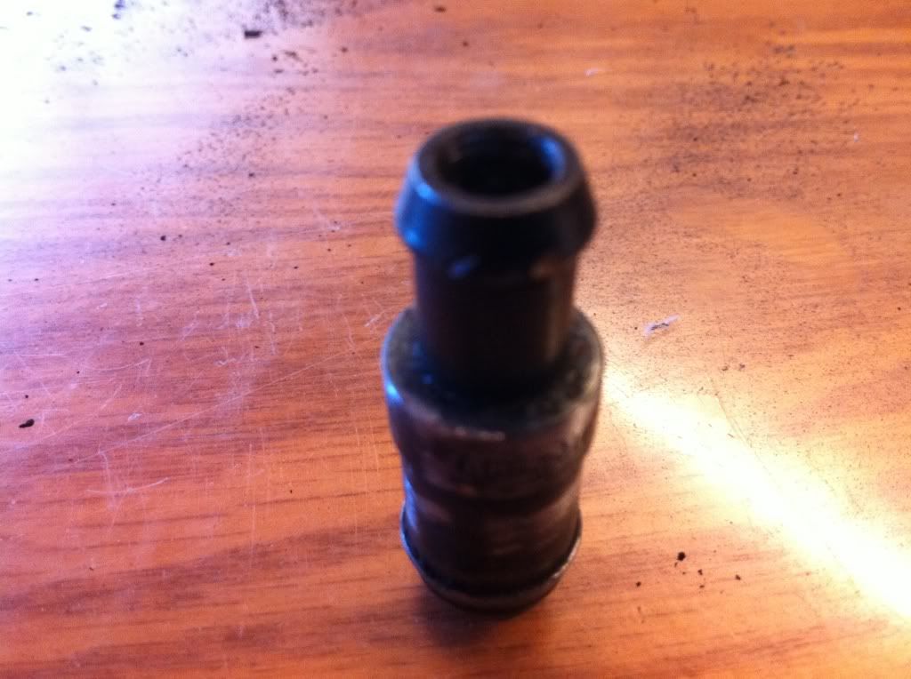 I know so what no big deal, right? Well when I drilled it out and ran the dremal around it a bit to clean it up I found this,,, 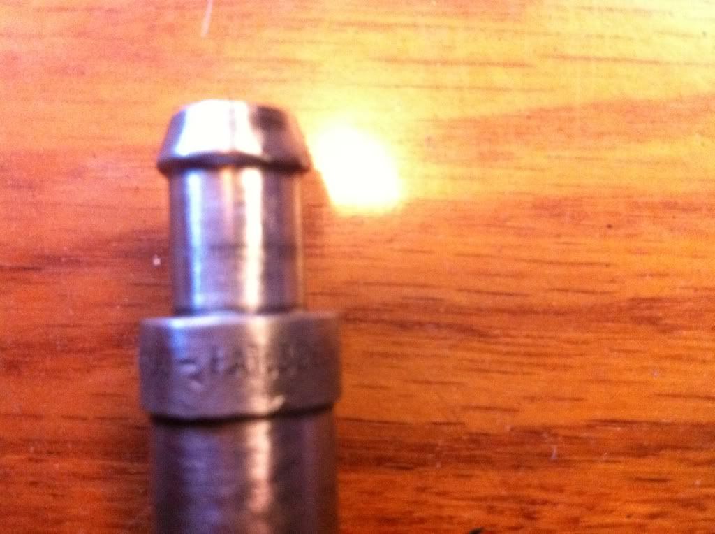 Ok I know the picture is a bit blurry but it says (FAT) Hmmm and again so what. The other side said,,,,, 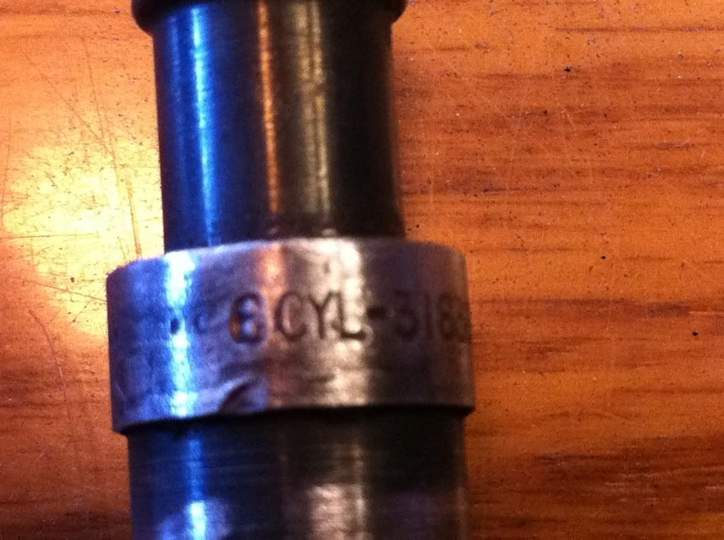 Yep you see it (6 CYL) So some how I found a part that is clearly meant to be on a FAT 6CYL(inders) motor. right?  So here is the almost finished part, I will take another picture tomorrow if I remember now that it is installed into the exhaust port air hole. 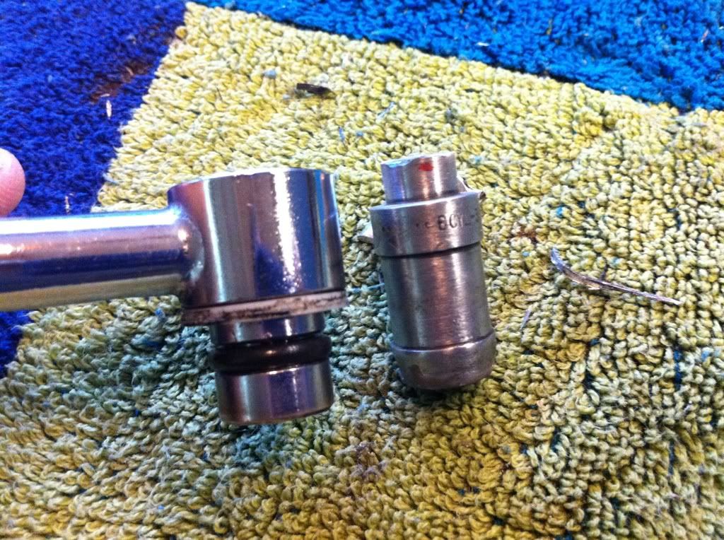 |
|
|
|
« Last Edit: February 16, 2011, 09:23:58 PM by fordmano »
|
Logged
|
83GS550 93XR650L TARD! 97WR250 99ValkyrieI/S Tri-tone 01YZ125(x2) 05DRZ-125
|
|
|
fordmano
Member
Posts: 1457
San Jose, CA. 1999 I/S 232 miles when bought 11/05
San Jose, CA.
|
|
« Reply #125 on: February 09, 2011, 02:41:12 AM » |
|
Now it's time to look at the mounting of the control panel for the cruise control.. I do not have access to any real machining equipment and I don't like the just glue it or tape it to a flat piece of sheet metel or some other bent flap of metal and I don't have any chrome straping or can't afford any custome chroming,, what to do what to do? So I happened to be at the hardware store and I found that some regular household electrical box pieces are flared or bulged not sure the correct term. but here is what I started with. 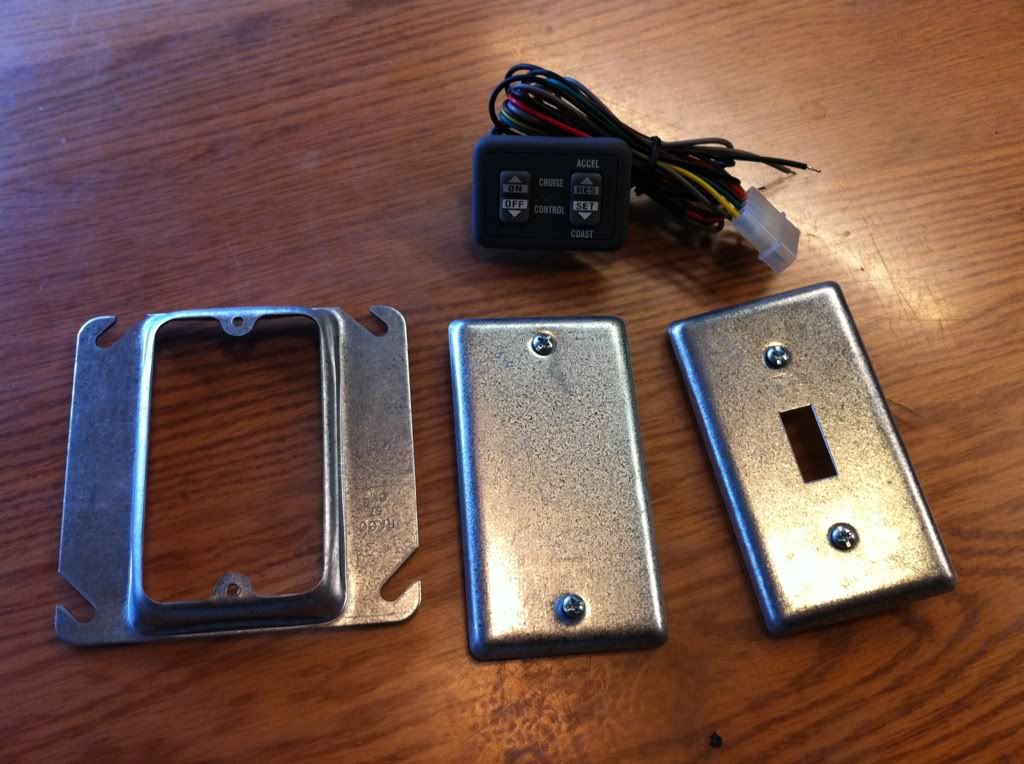 Hmmm might fit? 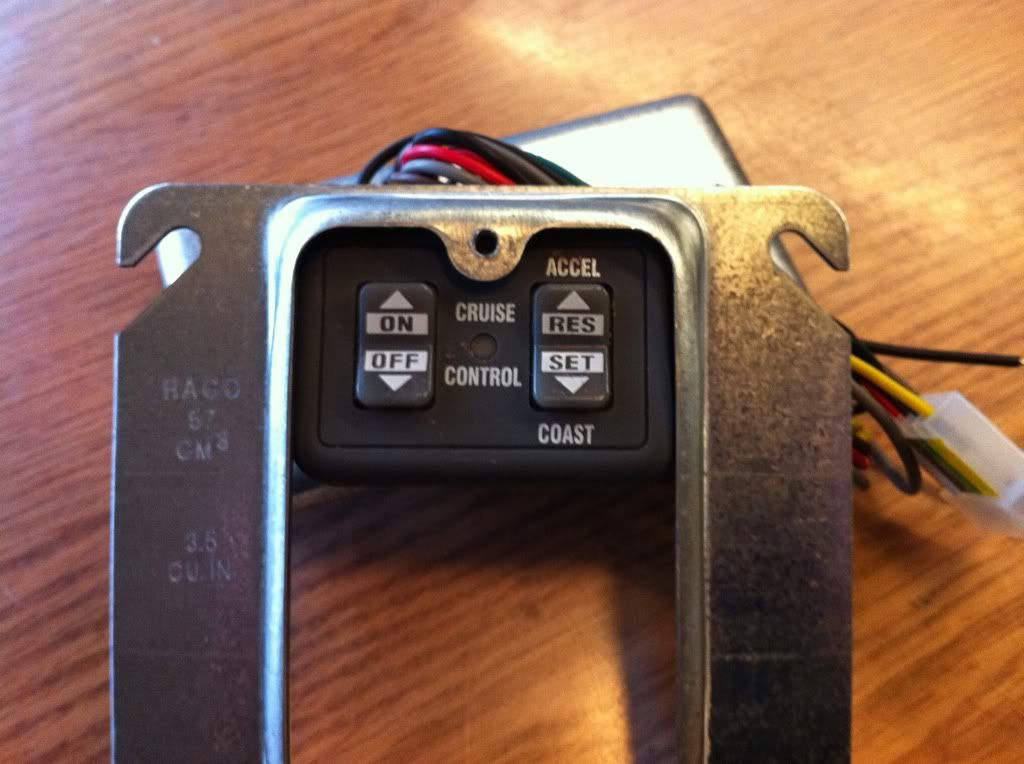 Well look at that, now I just need to trim it up a bit and maybe a little J-B weld will work out on this area. 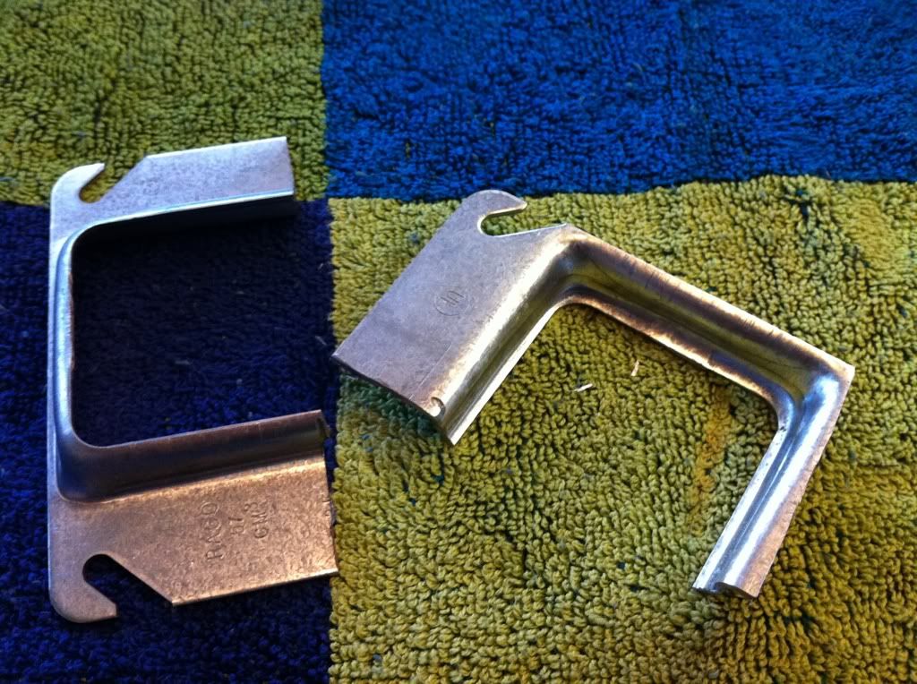 So basically I am making a case that will house the control panel. I was not sure I was going to share this part until I was completed with it but what the heck maybe it will give somebody a better idea later. 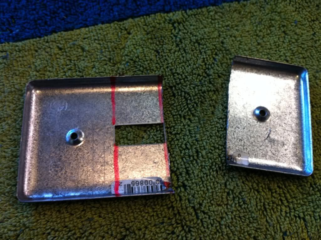 Lots of Dremel work with this part. 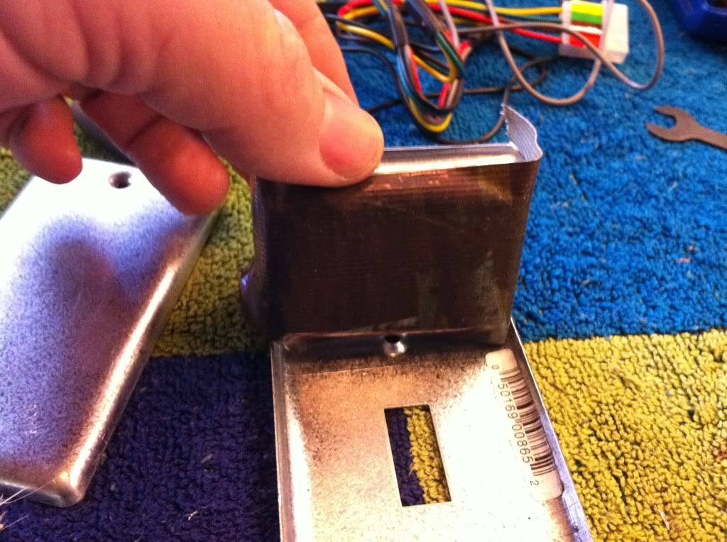 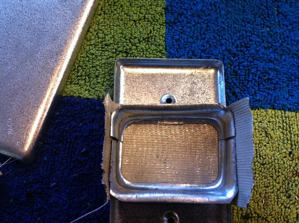 |
|
|
|
« Last Edit: February 16, 2011, 09:25:29 PM by fordmano »
|
Logged
|
83GS550 93XR650L TARD! 97WR250 99ValkyrieI/S Tri-tone 01YZ125(x2) 05DRZ-125
|
|
|
fordmano
Member
Posts: 1457
San Jose, CA. 1999 I/S 232 miles when bought 11/05
San Jose, CA.
|
|
« Reply #126 on: February 09, 2011, 02:43:41 AM » |
|
   It is taking form just slowly... More to come hopefully tomorrow... Again thanks again for following along. |
|
|
|
« Last Edit: February 09, 2011, 02:49:58 AM by fordmano »
|
Logged
|
83GS550 93XR650L TARD! 97WR250 99ValkyrieI/S Tri-tone 01YZ125(x2) 05DRZ-125
|
|
|
|
Ken Tarver
|
|
« Reply #127 on: February 09, 2011, 06:49:28 PM » |
|
great job on the horn,,,,looks new now
|
|
|
|
|
Logged
|
|
|
|
fordmano
Member
Posts: 1457
San Jose, CA. 1999 I/S 232 miles when bought 11/05
San Jose, CA.
|
|
« Reply #128 on: February 09, 2011, 09:58:18 PM » |
|
Thanks Ken,  Well I like it, it is not as pretty as when new but it is better than all scratched up and partially black. I may pull it back off later and redo the entire horn so it looks like it was supposed to look like that. |
|
|
|
|
Logged
|
83GS550 93XR650L TARD! 97WR250 99ValkyrieI/S Tri-tone 01YZ125(x2) 05DRZ-125
|
|
|
fordmano
Member
Posts: 1457
San Jose, CA. 1999 I/S 232 miles when bought 11/05
San Jose, CA.
|
|
« Reply #129 on: February 09, 2011, 10:07:23 PM » |
|
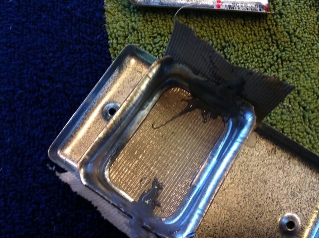
So today I spent a little bit of time and did some more work on the mount for the Cruise Control (controls). This is after I pulled the clamps off it after sitting all night and drying. 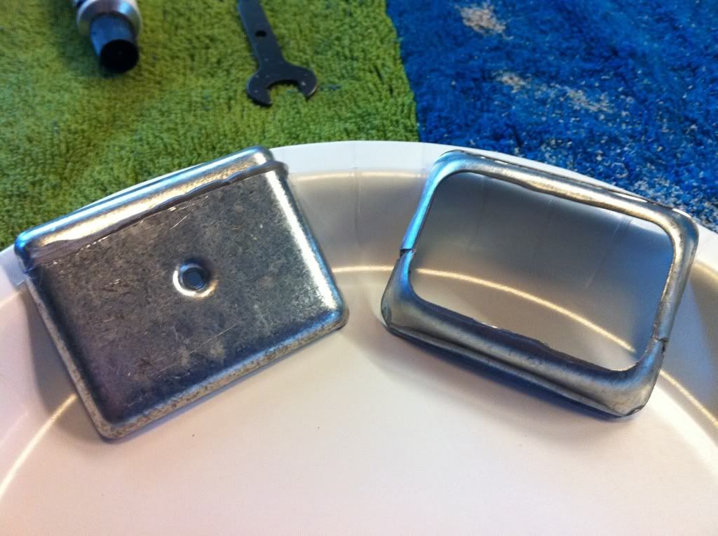 Here is another look at what it will look like when completed but hopefully a bit prettier than this. 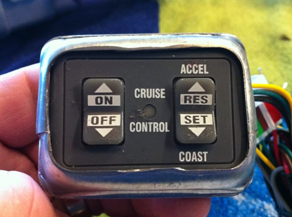 I will sand all the edges down and fill the low spots back in with J-B weld like a bondo then smooth it back out tomorrow. 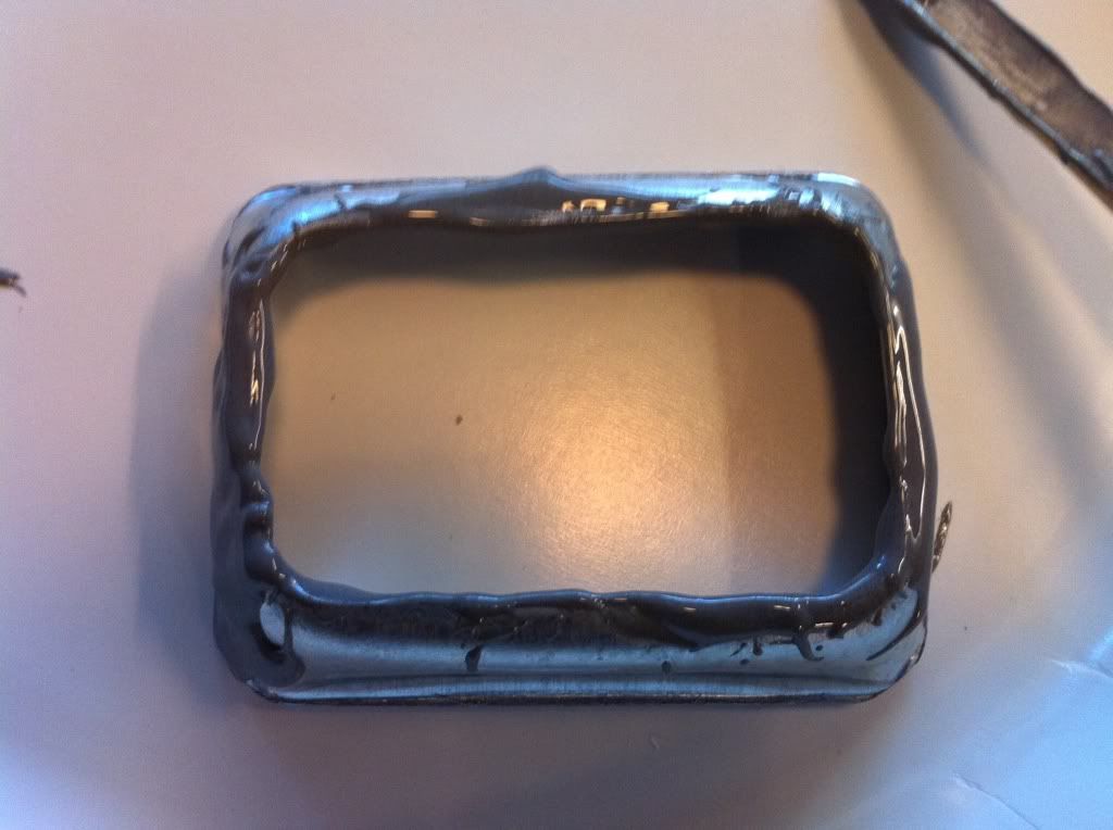 Here are the front and back plates with the J-B weld filled back in and ready to dry over night. 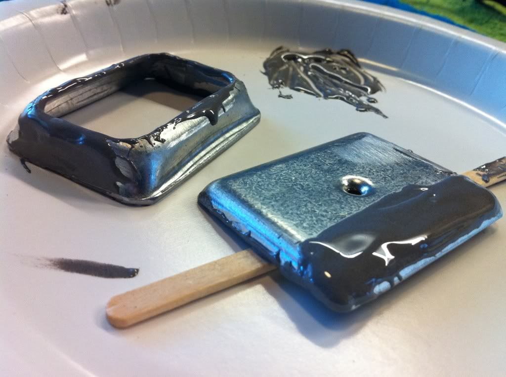 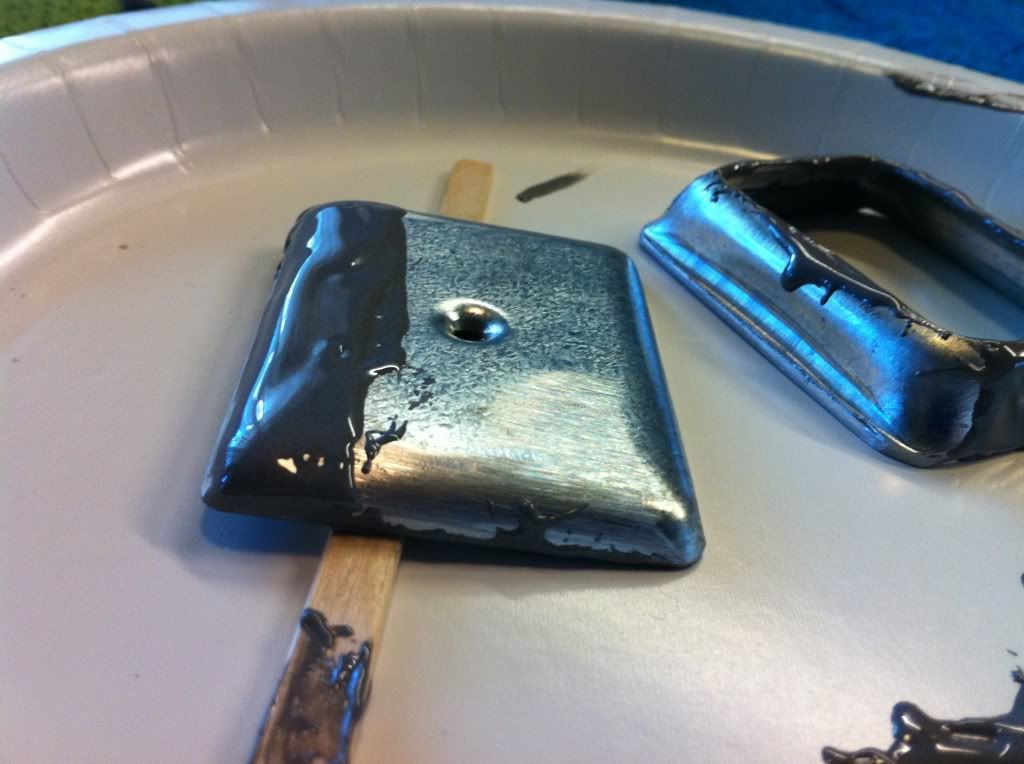 |
|
|
|
« Last Edit: February 16, 2011, 09:26:41 PM by fordmano »
|
Logged
|
83GS550 93XR650L TARD! 97WR250 99ValkyrieI/S Tri-tone 01YZ125(x2) 05DRZ-125
|
|
|
fordmano
Member
Posts: 1457
San Jose, CA. 1999 I/S 232 miles when bought 11/05
San Jose, CA.
|
|
« Reply #130 on: February 09, 2011, 10:18:36 PM » |
|
This is the other area I burnt up a few minutes on today. I wanted and easy to see and read Volt meter, so Where to put it? Well I am replacing the 3 switches for my factory fog lights my auxillary driving lights and my under belly real yellow fog lights. The Factory fog light switch was installed as per Honda directions when the Original owner picked up the Bike from dealer, I never liked the location or the look of the switch much anyway but the empty hole in the left side radiator pod would have sucked and looked terrible if left empty. So this is where I will be adding my Volt meter. I am using the Kuryakn Black LED volt meter. 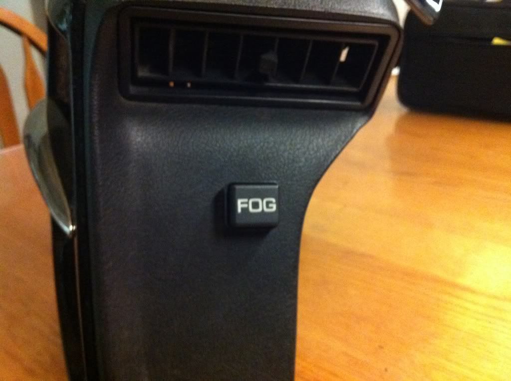 Yes I will need to do a bit of fiddling with it to make it look nice after mounted, but that should be easy. 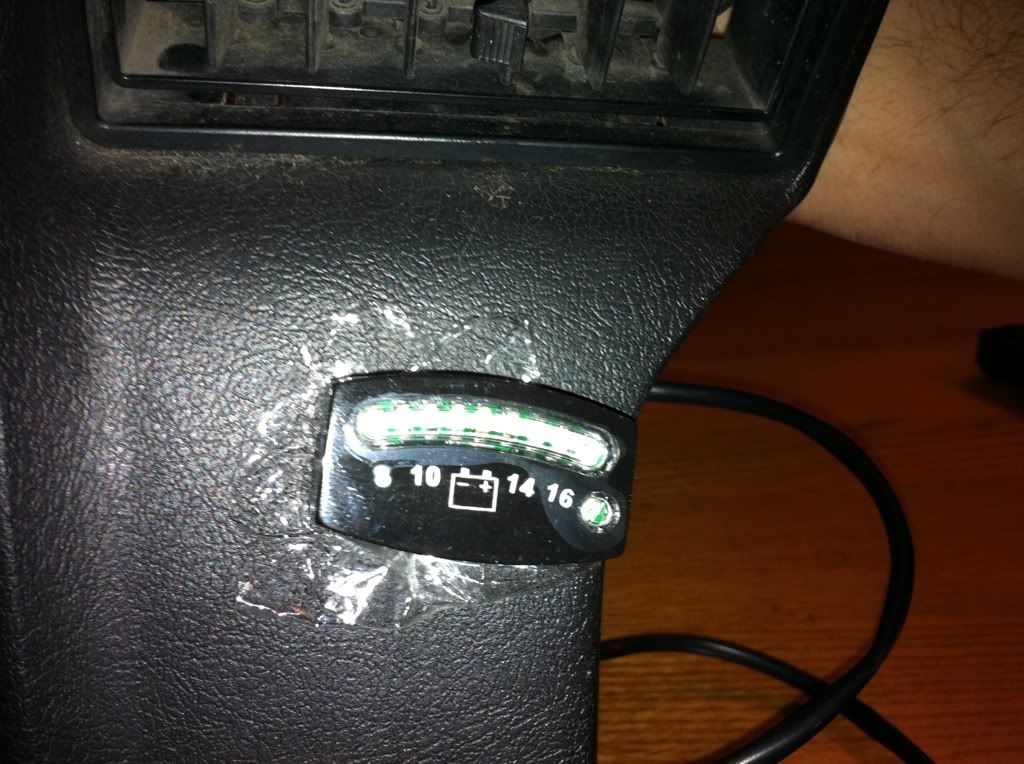 Lights off. 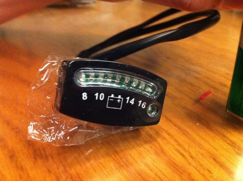 Lights on, Yep it works, I powered it up using a 9volt battery and just as the directions state it lit up all the lights starting on the left and went across to the right and then they all flash and after that it settles back down and show actual current Voltage. 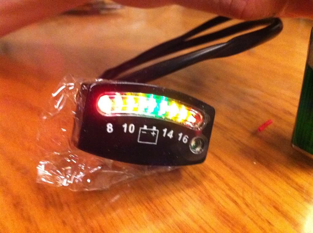 |
|
|
|
« Last Edit: February 16, 2011, 09:28:26 PM by fordmano »
|
Logged
|
83GS550 93XR650L TARD! 97WR250 99ValkyrieI/S Tri-tone 01YZ125(x2) 05DRZ-125
|
|
|
fordmano
Member
Posts: 1457
San Jose, CA. 1999 I/S 232 miles when bought 11/05
San Jose, CA.
|
|
« Reply #131 on: February 10, 2011, 01:22:33 AM » |
|
Recap-update, list as it sits now.
1 ) New Front tire, AVON. (DONE)
2 ) New Rear tire, AVON. (DONE)
3 ) New Front brake pads. (DONE)
4 ) New Rear brake pads. (DONE)
5 ) New Rubber dampers in the final drive of the rear wheel. (DONE)
6 ) New Galfer Braided SS clutch line (DONE)
7 ) New Galfer Braided front brake line. (DONE)
8 ) New Galfer Braided rear brake line. (DONE)
9 ) New Galfer DOT4 brake fluid in all lines. (DONE)
10) New O-Rings rear drive, all 3 O-Rings (DONE)
11) New LED turns signals added under bags. (DONE)
12) New LED extra brake lights. (DONE)
13) New Rear under Trunk Brake light with Air inlet for shocks. (DONE)
14) New Rear Progressive 416 Air shocks with new mounting hardware. (DONE)
15) Install completely custom rebuilt RaceTech front forks. (DONE)
16) New Chrome master cylinder covers Clutch & Brake. (DONE)
17) Flush and refill radiator coolant. (DONE)
18) Remove all smog related equipment. (DONE)
19) Install new Pingel Petcock. (DONE)
20) Install Chrome accents on Intake runners. (DONE)
21) Clean up intake runner internal walls. (DONE)
22) Install new intake runner O-Rings. (DONE)
23) Install HID headlights. (DONE)
24) Modify and install new Polk Audio front speakers. (DONE)
25) Rebuild carbs and install all new O-rings and rubber pieces. (DONE)
26) Install new #38 and #105 Carb jets. (DONE)
27) Modify Battery compartment for Cruise control install. (DONE) (changed mind will mount in fairing)
28) Install Battery tender adapter cable. (DONE)
29) Replace Differential fluid with Synthetic. (DONE)
30) Cleanup repaint and beautify Stebel air horn and remount. (DONE)
Still to finish on my list.
1) Install cruise control system. (partial)
2) Install new switch block for forward lighting. (partial)
3) Install new Voltage meter. (partial)
4) Install 400watt Pyle 4 channel amplifier. (partial)
5) Install power block under seat and under fairing for lighting switches and amplifier power routing. (partial)
6) Install my Dan-Mark electric fuel shut off valve. (partial)
7) Re-Sync the carbs after all the air box and intake and cruise control is completely installed.
8:) I may try and get a fellow rider that owns a shop to use his tail pipe sniffer to verify my fuel mixture is close to correct and adjust the jets and needles if needed later.
Things on original list that will NOT be done at all during this project list.
1) Replace head bearings,,, after having the front end torn down and having 2 real mechanics feel the head bearings it has been decided that the currently installed (factory original) are still good.
2) Install mini amps, decided that it would be best to buy a quality amplifier instead of these little junky Chinese made amplifiers that when I tried to hook them up last time I could not get them to work reliably on the Valkyrie stereo.
I hope that about covers it, for now.
Again thanks for following along with all of this, I truly hope something in here helps at least one person with a project or sparks a cool idea for an upgrade.
|
|
|
|
« Last Edit: February 16, 2011, 09:32:10 PM by fordmano »
|
Logged
|
83GS550 93XR650L TARD! 97WR250 99ValkyrieI/S Tri-tone 01YZ125(x2) 05DRZ-125
|
|
|
fordmano
Member
Posts: 1457
San Jose, CA. 1999 I/S 232 miles when bought 11/05
San Jose, CA.
|
|
« Reply #132 on: February 10, 2011, 09:43:31 PM » |
|
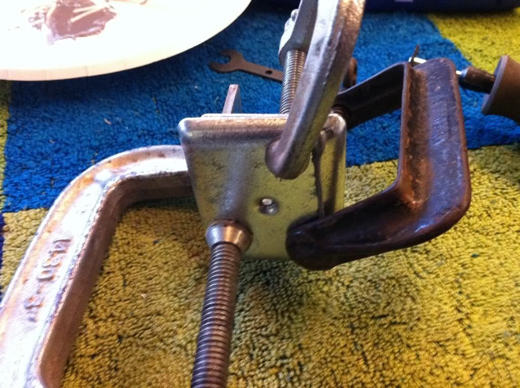
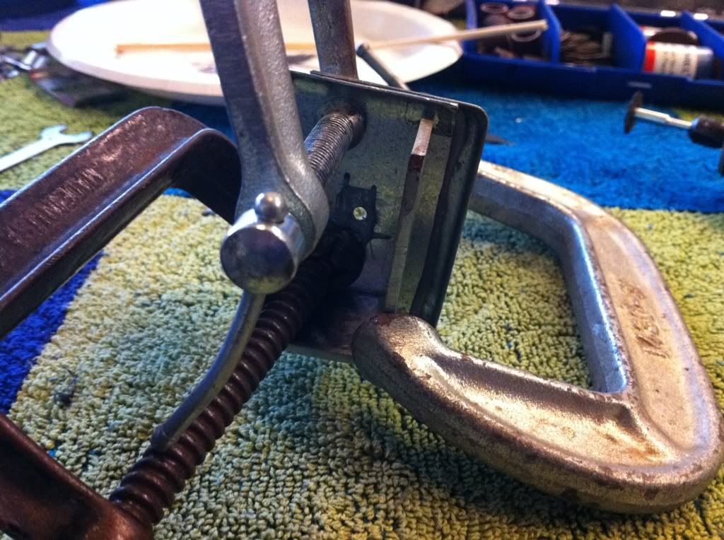
Todays updates, Got a bit more done on the control panel for the cruise control. It is coming along slowly but it is coming along, so that is a good thing. Front cover, scroll back and compare it to what it looked like yesterday. I think this is improvement. 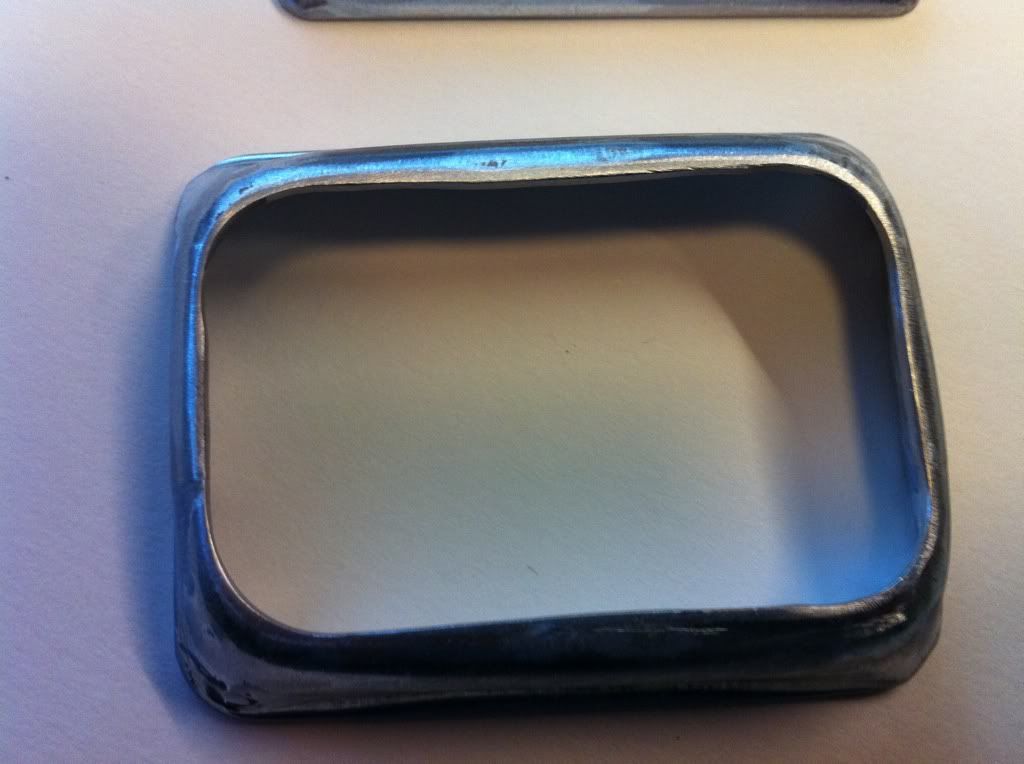 Rear cover, also much better. 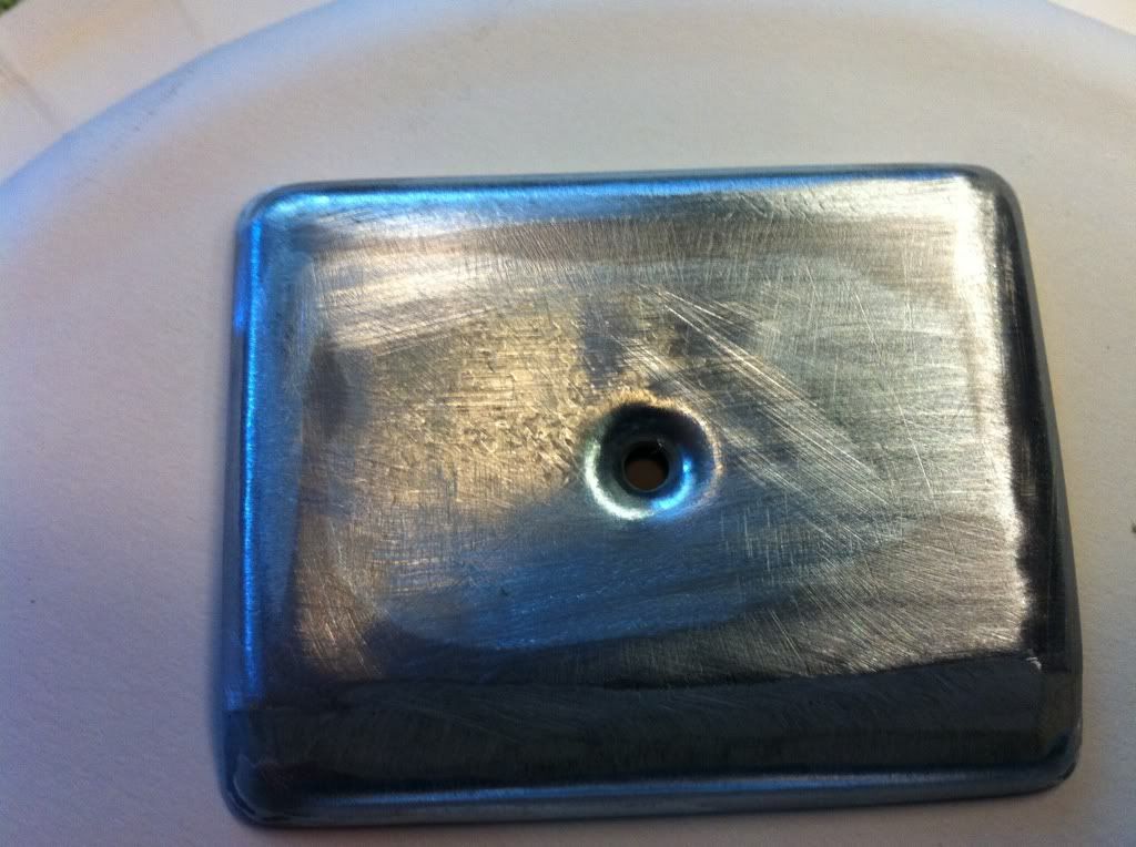 So how to attach it to the bike??? Well I just don't trust using only the double backed tape that is provided so that is why this control panel (box) is being made. So I need to attach some sort of threads to the back wall. I got an idea, since the back wall is actually doubled up why not relieve a small area and drill a hole then run a bolt through it and use some more J-B weld to hold it in place.  The slot/hole cut in the middle of the rear plate is for the wires to protrude out of this will help hide them when I make the actual mounting plate that will hold the control box onto the Handle bars. 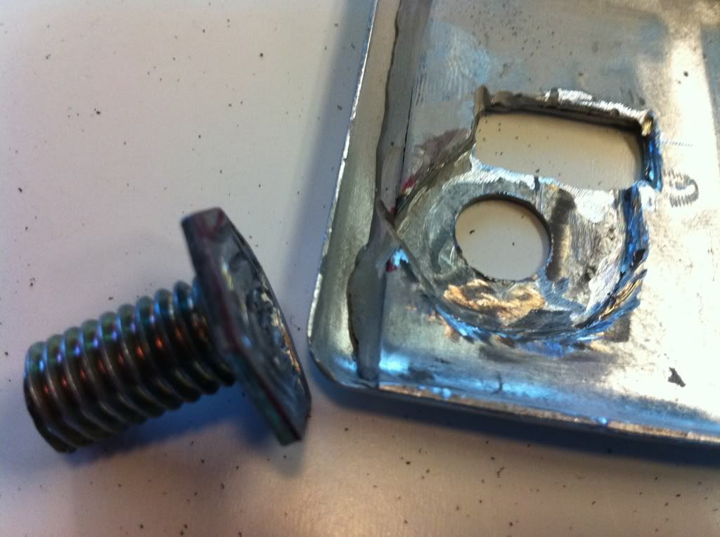 Here is the relief I cut out for the bolt head to reside in. 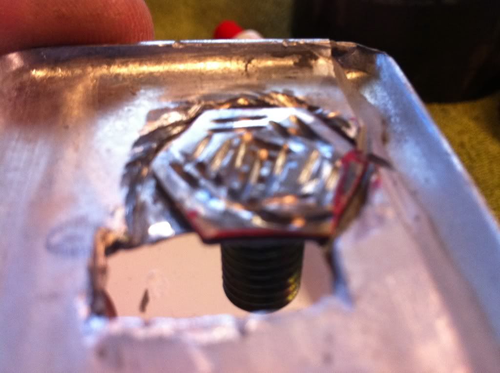 You can see the slots I ground into the head of the bolt after I had gouornd it to a very thin head, probably a 1/16th" thick. The grooves were cut in to give the J-B weld a place to bite and hold onto then I decied to just drill a hole and run the bolt through from the iside of the box seemed like a more sturdy solution. |
|
|
|
« Last Edit: February 10, 2011, 10:07:05 PM by fordmano »
|
Logged
|
83GS550 93XR650L TARD! 97WR250 99ValkyrieI/S Tri-tone 01YZ125(x2) 05DRZ-125
|
|
|
fordmano
Member
Posts: 1457
San Jose, CA. 1999 I/S 232 miles when bought 11/05
San Jose, CA.
|
|
« Reply #133 on: February 10, 2011, 09:56:45 PM » |
|
Here is a look at the inside of rear plate with the J-B Weld in place and the bolt held in place for the drying time. 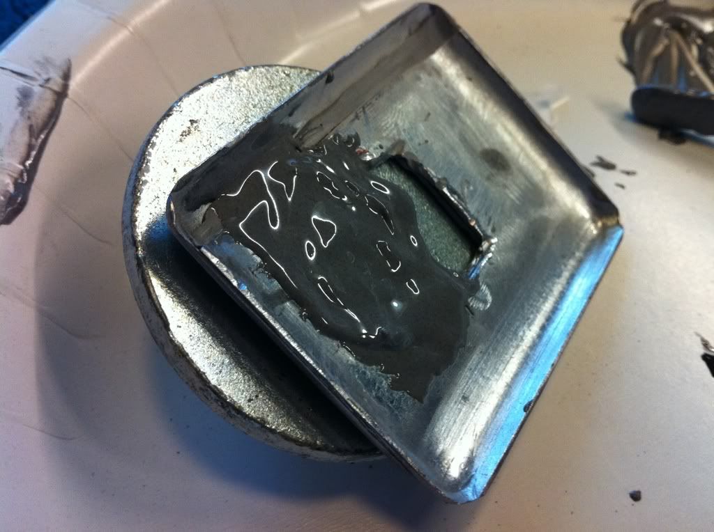 Here is the setup I used to keep the Bolt held tight while the J-B Weld is drying over night. 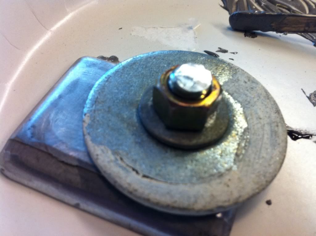 I should have shown these 2 pictures earlier sorry I got a little bit ahead of myself again. This the almost finished look of the 2 halves, I taped them together and ran them on the belt sander and even up the outer edges of the box. 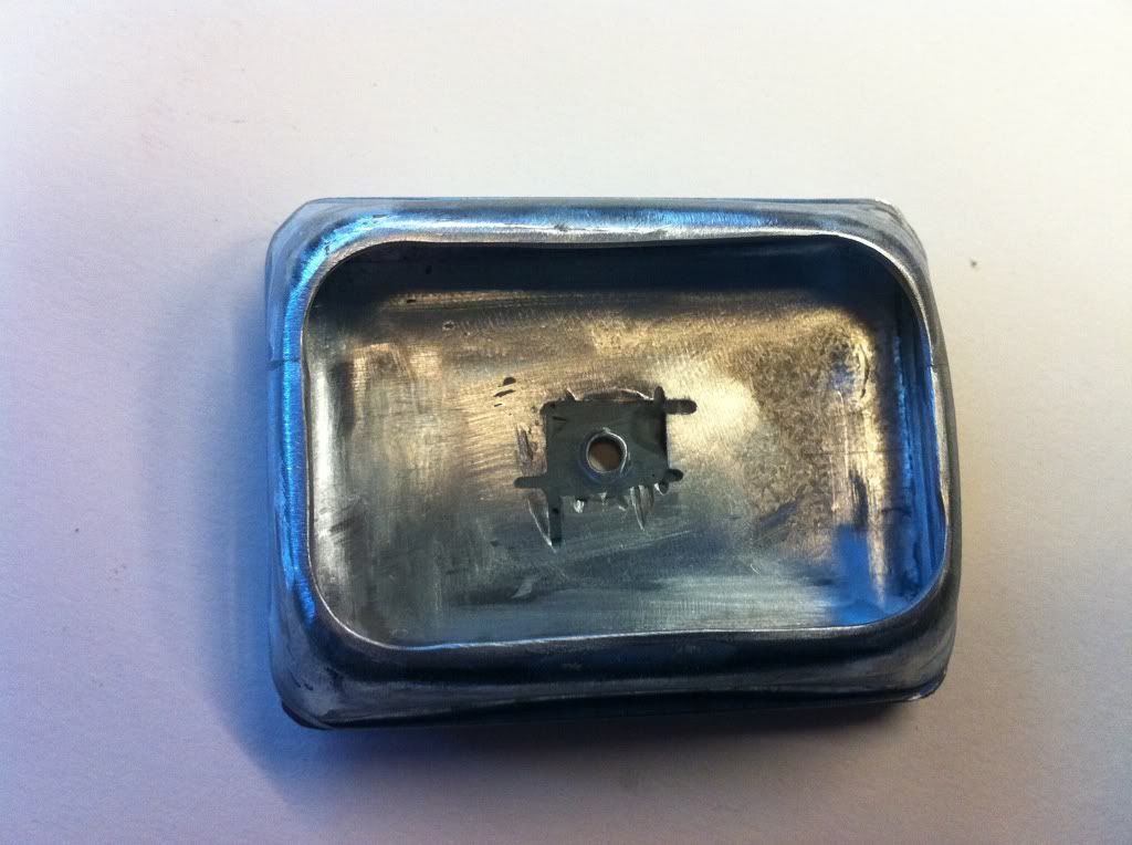 They seem to fit together fairly well. 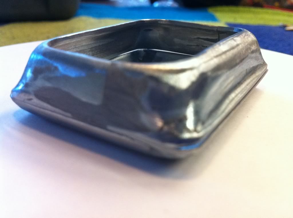 I am not so sure I like how the Cruise control panel fits inside of the front of the box? It is not perfect but I think it will work out with a little bit more sweat and frustration. I did install some 3M double back tape on the inside it is kind of a thin foam backing and will help provide a solid/stable fit when the box is finished and closed up. I will probably end up having to glue the 2 halves together I was planning on using very small screws glued to the front cover and run out the back panel then loctite very small nuts onto the threads thet protruded out of the back of panel but there just is not enough room to install the screws inside on any side of the plastic control. 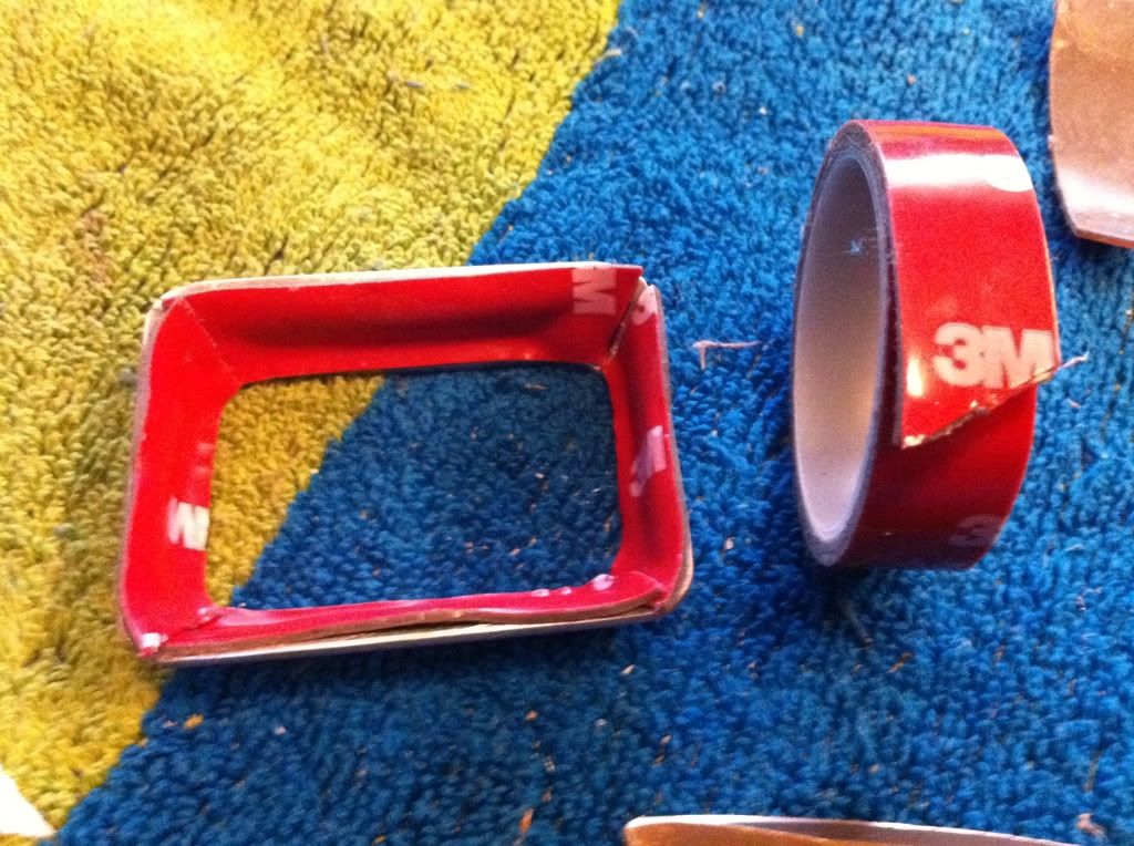 |
|
|
|
« Last Edit: February 10, 2011, 10:08:02 PM by fordmano »
|
Logged
|
83GS550 93XR650L TARD! 97WR250 99ValkyrieI/S Tri-tone 01YZ125(x2) 05DRZ-125
|
|
|
fordmano
Member
Posts: 1457
San Jose, CA. 1999 I/S 232 miles when bought 11/05
San Jose, CA.
|
|
« Reply #134 on: February 10, 2011, 10:05:59 PM » |
|
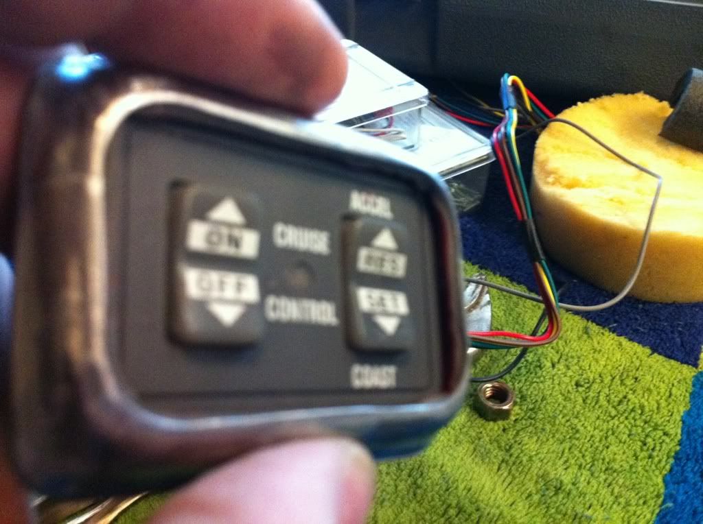 I may relieve the inside walls a little bit more to allow the control panel to sit more forward inside the box 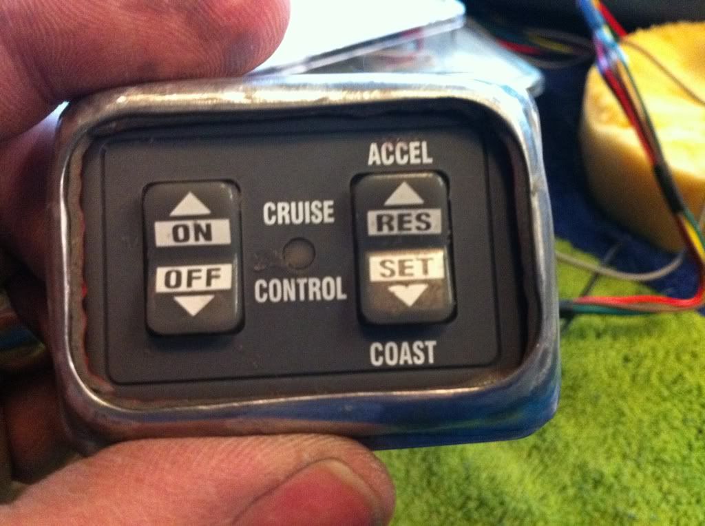 Not bad considering this has all been done by eye and with only a Dremel rotary tool a 3" wide belt sander turned upside down and a cordless hand drill. Sure wish I had a real Mill and a good bench grinder not to mention a few other full size real shop tools. The picture below is actually taken before I added the 3M foam backed double back tape. 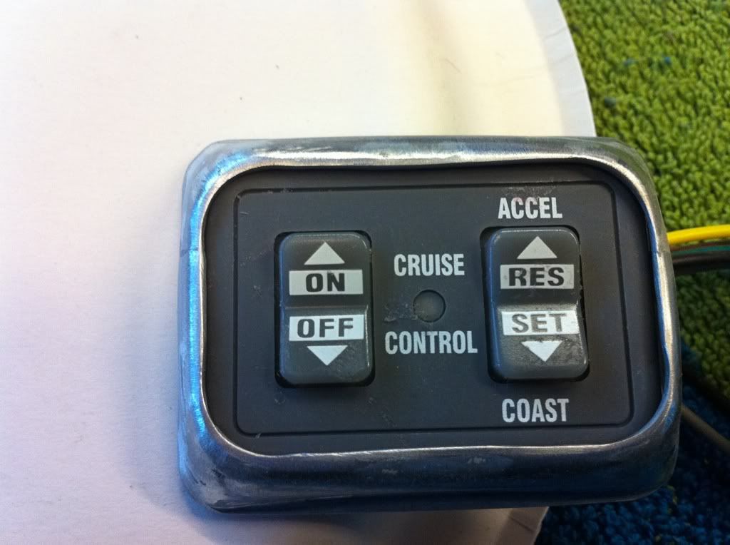 I need to decide if the box will get painted with that Chrome paint or Honda Red for the box with a black painted bracket to attach to handle bars or just all Black, or maybe black bracket, black back of box and Honda Red on the front cover only? |
|
|
|
« Last Edit: February 10, 2011, 10:09:14 PM by fordmano »
|
Logged
|
83GS550 93XR650L TARD! 97WR250 99ValkyrieI/S Tri-tone 01YZ125(x2) 05DRZ-125
|
|
|
fordmano
Member
Posts: 1457
San Jose, CA. 1999 I/S 232 miles when bought 11/05
San Jose, CA.
|
|
« Reply #135 on: February 12, 2011, 02:23:11 AM » |
|
Here is a picture of the rear of the box for housing the cruise control (controls), I may need to trim those threads down a little bit when I figure out the rear mounting bracket. 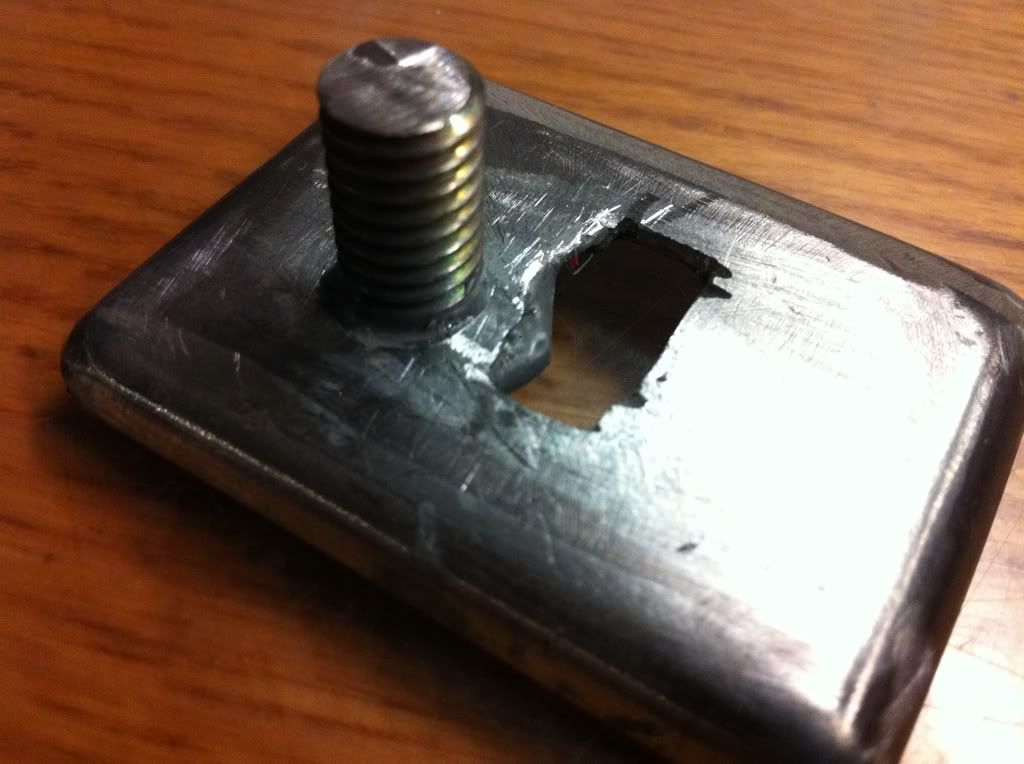 And here is a little look at what the rear will look like with the wires run through it and headed toward the center of the bars to the rest of the system. 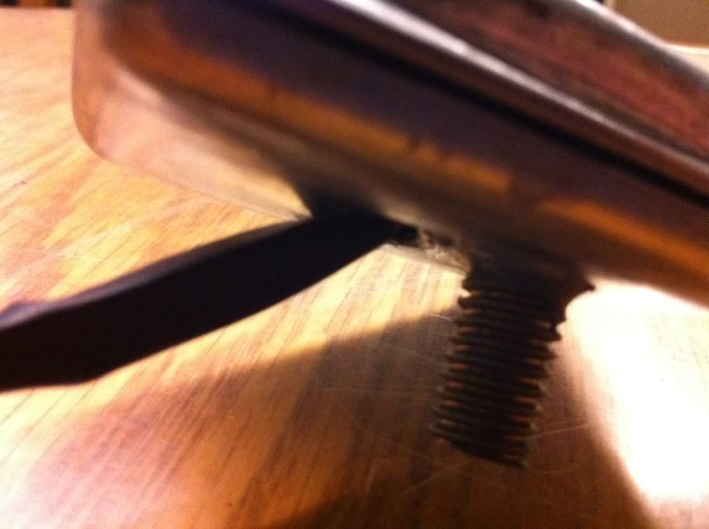 I forgot to take a picture last night but I will return tomorrow with a picture of this next step. I did a little trimming on the 3M double sided foam tape, still need to work on the inside so I get the actual control face to fit a bit closer toward the front of the box. I might end up just filling the inside with silicone and pressing the control panel into the front cover and letting it adhere in there and live with it however it looks. |
|
|
|
« Last Edit: February 12, 2011, 02:36:42 AM by fordmano »
|
Logged
|
83GS550 93XR650L TARD! 97WR250 99ValkyrieI/S Tri-tone 01YZ125(x2) 05DRZ-125
|
|
|
|
PhredValk
|
|
« Reply #136 on: February 15, 2011, 10:45:35 AM » |
|
Thought I'd bump this up to the top with a question.
In your Jan 05 pix we see a pair of blue lights mounted under the fairing. What wattage are they, and how bright.
I've been looking for a good set of 'critter lights' for my I/S. Would have to be bright enough to see the side of the road/ditches far enough out to see deer etc long before they're on the road, and be small enough to mount where yours are. I've seen some 55 watt Halogen and PIAA lights like that, but don't know if they will really do what I need them to.
Great thread, and I will try some of your ideas, if I may; especially on the Cruise install
Keep it up, and thanx,
Fred.
|
|
|
|
|
Logged
|
Growing old is mandatory, growing up is optional.
VRCCDS0237
|
|
|
|
5_19
|
|
« Reply #137 on: February 15, 2011, 10:58:50 AM » |
|
Thought I'd bump this up to the top with a question.
In your Jan 05 pix we see a pair of blue lights mounted under the fairing. What wattage are they, and how bright.
I've been looking for a good set of 'critter lights' for my I/S. Would have to be bright enough to see the side of the road/ditches far enough out to see deer etc long before they're on the road, and be small enough to mount where yours are. I've seen some 55 watt Halogen and PIAA lights like that, but don't know if they will really do what I need them to.
Great thread, and I will try some of your ideas, if I may; especially on the Cruise install
Keep it up, and thanx,
Fred.
I use the same lights. Bought them at Oreilly Autoparts for about $30. 50 Watt H4 off road each and they light up the road! TJ |
|
|
|
|
Logged
|
 Most motorcycle problems are caused by the nut that connects the handlebars to the saddle. IBA # 45723 2001 Honda Valkyrie Standard (Sold after 9 years) 2009 BMW R1200 GSA |
|
|
fordmano
Member
Posts: 1457
San Jose, CA. 1999 I/S 232 miles when bought 11/05
San Jose, CA.
|
|
« Reply #138 on: February 15, 2011, 10:02:57 PM » |
|
Fred, first off I think the PIAA lights will be brighter but a LOT more expensive I am sure. I believe these are the lights you are asking about. I got them at WalMart a couple years ago. I think I gave about $16.xx or $18.xx for them I thought they were listed as 55WATT but I could be wrong they may only be 50Watts. I have them swiveled very slightly outward so to help brighten up the edges of the road. I really only added them as an “UH OH backup source of light”. Years ago I was out hunting in my Suburban and we lost the headlight circuit and had to use a spot light hanging out the window to guide us back to our campsite and my buddy about got frost bite so I swore I would NEVER EVER be without a completely separate set of lights away from my headlight circuit on ALL of my vehicles. These were listed on the package as driving lights. EDIT: I found the information on the headlight bulbs as a reference for you. Directly from PIAA website. Twin Pack 10904 Single Pack 10934 Bulb Type H4 Wattage 60/55w = 135/125w, 4100K Technology Intense White 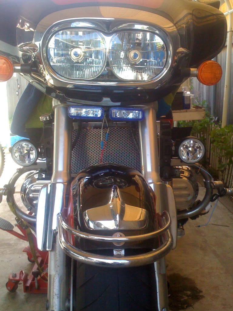 Here is an older picture with them lit up you can get a slight idea of how they look compared to the other lights. The headlights in this are the PIAA 60/55 watt Intense white I think that's what they are called and I think they are on the low beams here. And the POD lights are also PIAA 55watt intense white bulbs. EDIT: here is the info on the POD foglights from PIAA website. Twin Pack 10903 Single Pack 10933 Bulb Type H3 Wattage 55w = 100w, 4100K Technology Intense White 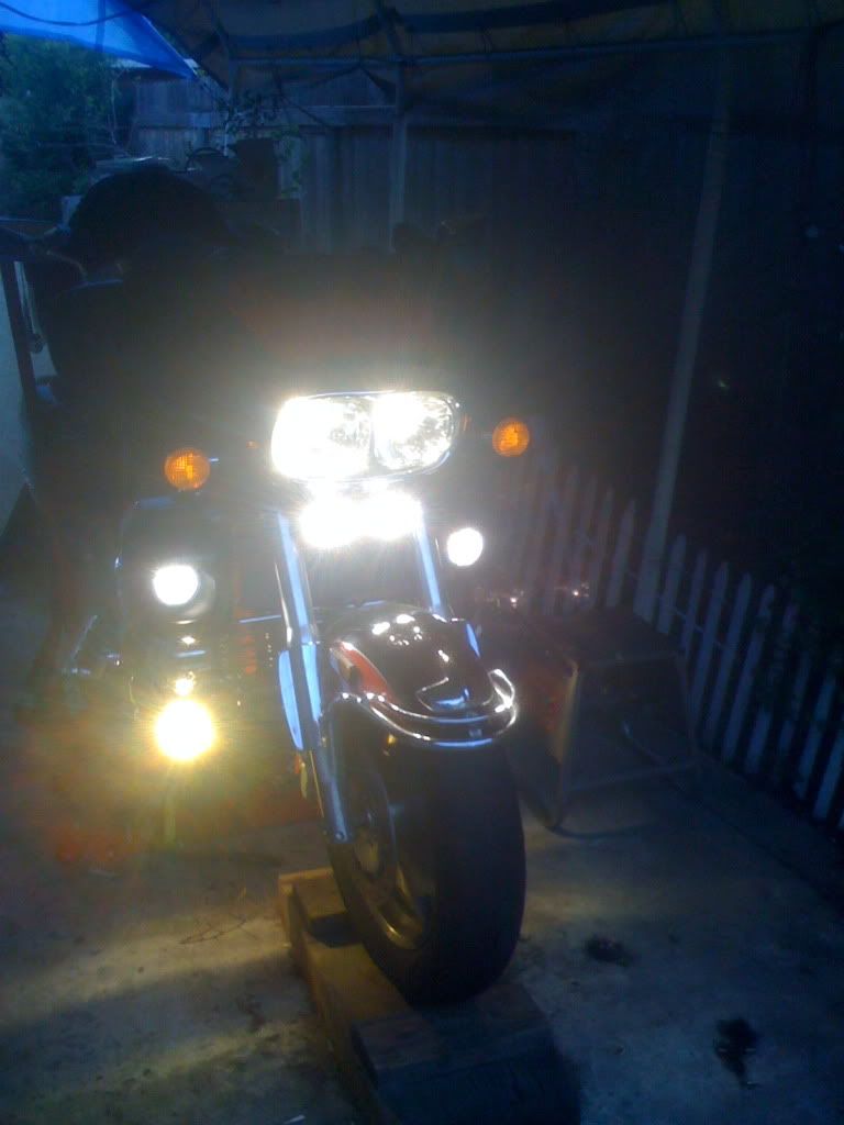 The lights on the very bottom are a very cheap set of real yellow FOG lights from WalMart I think I gave around $14.xx for that set 35watts I hope that answers the question to your liking there Fred. I went out and took a couple close up pictures of the bracket for you Fred just incase you are wondering how that were mounted. 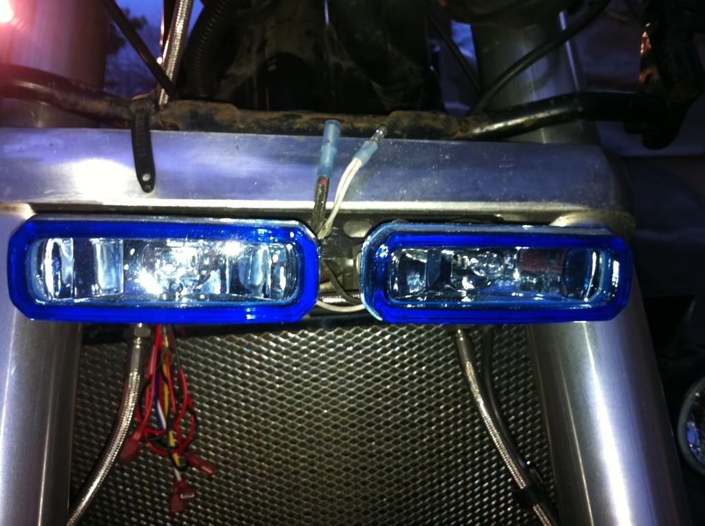 I used the bolts that stick through the lower triple tree that hold the frame work that holds the Fairing on the Interstate then just found some angle iron and drilled it to fit then attached the brackets that came with the lights to the front of it. It did take a little bit of bending and grinding to fit as close as it does to the bottom of the fairing. I wanted the lights to disapear as much as possible uder the fairing but what I really wanted was to use the lower vents on the fairing to actually hide the lights behind the vents. I just could not get it to fit that way in the amount of time I was willing to spend on them. This picture is from uner the tripple tree pointed toward the front of the bike. 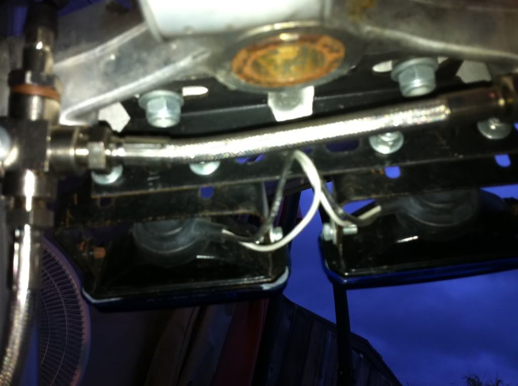 Here is a close up just so you can see the mounting hardware a little better. 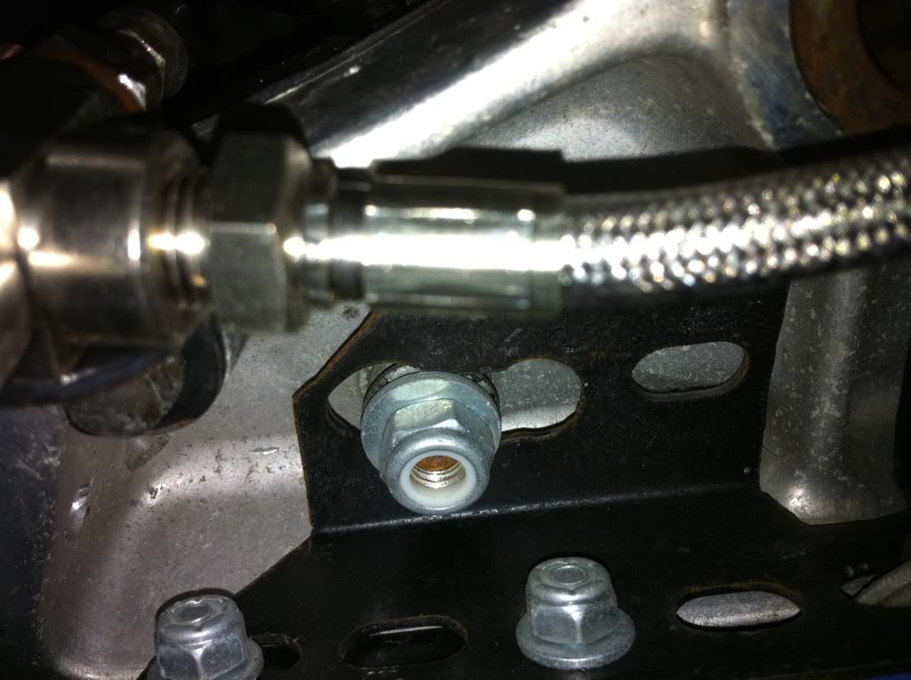 |
|
|
|
« Last Edit: August 29, 2013, 11:47:32 PM by fordmano »
|
Logged
|
83GS550 93XR650L TARD! 97WR250 99ValkyrieI/S Tri-tone 01YZ125(x2) 05DRZ-125
|
|
|
fordmano
Member
Posts: 1457
San Jose, CA. 1999 I/S 232 miles when bought 11/05
San Jose, CA.
|
|
« Reply #139 on: February 15, 2011, 10:13:18 PM » |
|
Here are just a couple more pictures I took for you Fred figured more is better right. 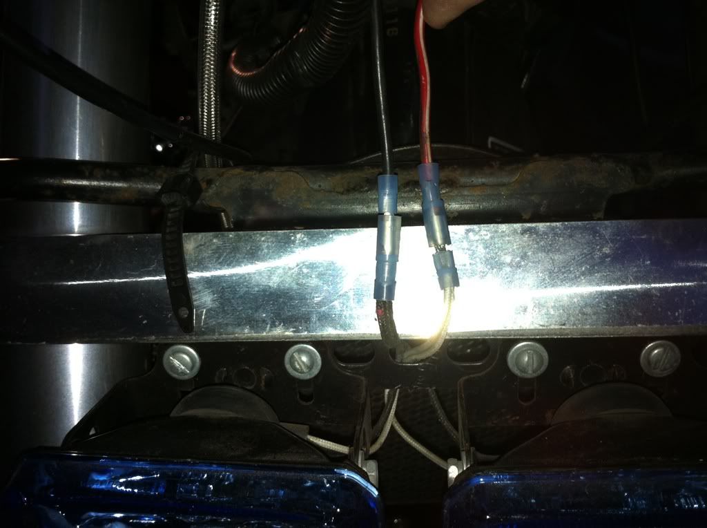 Just a suggestion, but these lights have a drain or vent slot cut into them and I placed it down as to act as a drain if they ever get any water up in them it will be able to get back out. That fuzzy line in the center just below the blue lense is the vent or slot. 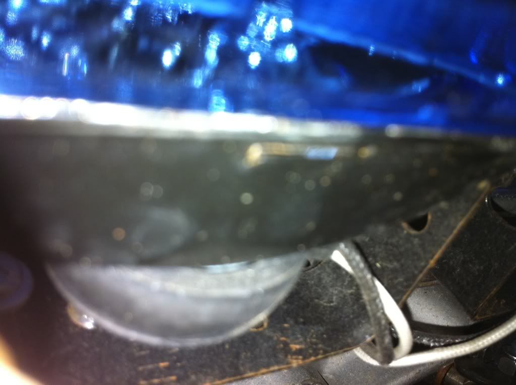 Here is a side view of the forward section of the mount. Taken from the side. 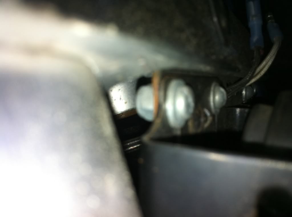 And this one is looking UP from directly under the triple tree. 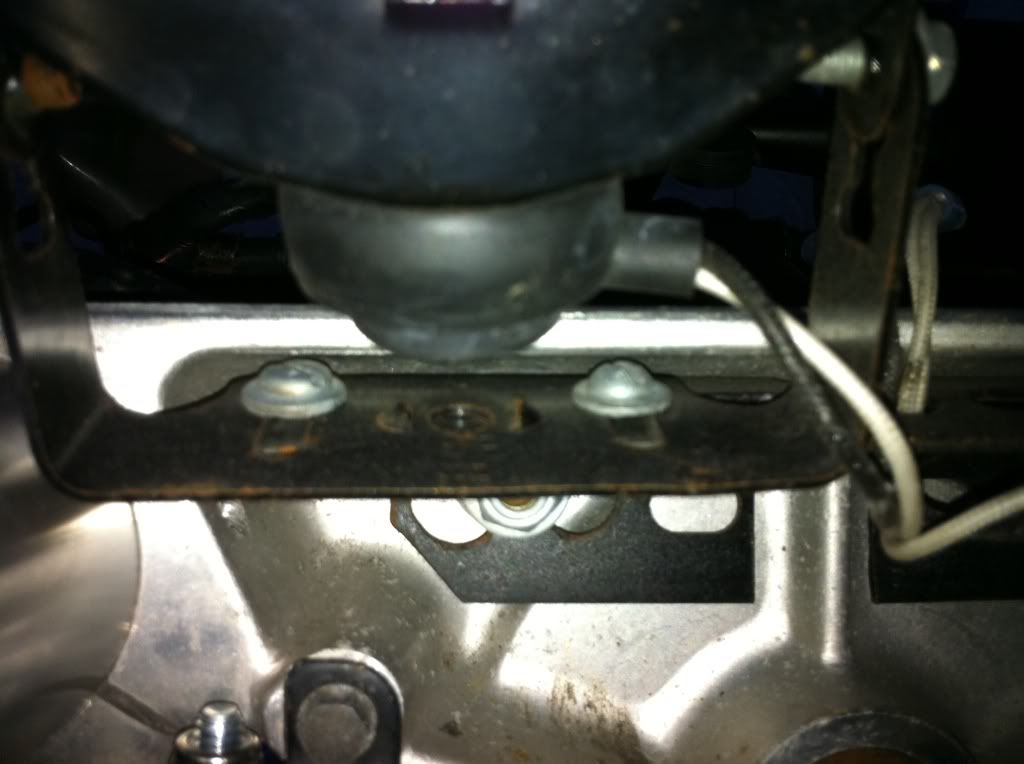 I hope these help you out with your project Fred. |
|
|
|
« Last Edit: February 15, 2011, 10:26:15 PM by fordmano »
|
Logged
|
83GS550 93XR650L TARD! 97WR250 99ValkyrieI/S Tri-tone 01YZ125(x2) 05DRZ-125
|
|
|
fordmano
Member
Posts: 1457
San Jose, CA. 1999 I/S 232 miles when bought 11/05
San Jose, CA.
|
|
« Reply #140 on: February 15, 2011, 10:40:05 PM » |
|
I did not get much at all done today or yesterday (Valentines day), but I did get some of the soldering and measuring of wires done for the Amplifier install. So lets get started. 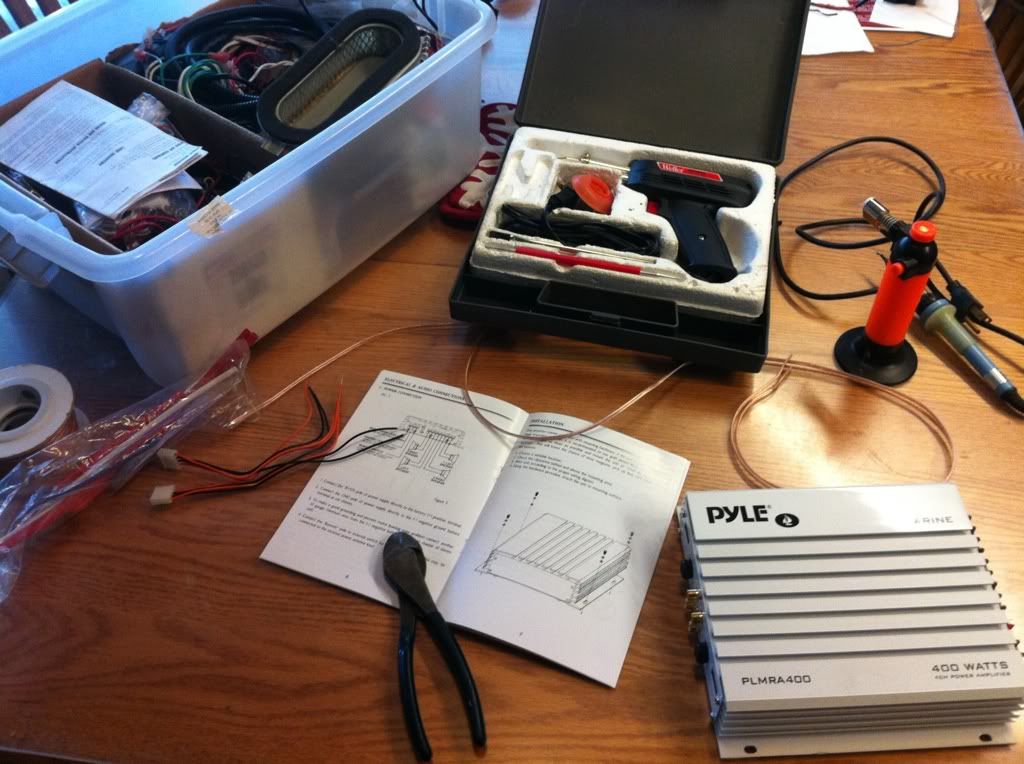 Gotta have my work area and tools ready. Here is the Wires in different stages, you can see plain striped wires that have been tinned and soem that have not been tinned yet, the crimp connectors and heatshrink tubing waiting to be installed. You can also see the first set of wires actually connected to the amp and completed. I like using the heat shrink tubing and also soldering a crimped connection when I can. 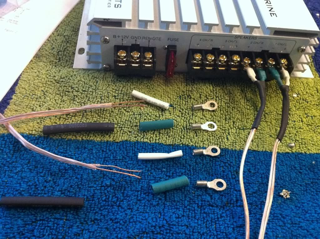 Yep I got the amplifiers side all done. 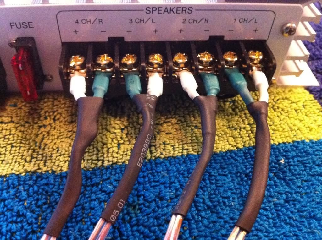 This is all the wires for the speakers and the power source all rolled up and waiting. 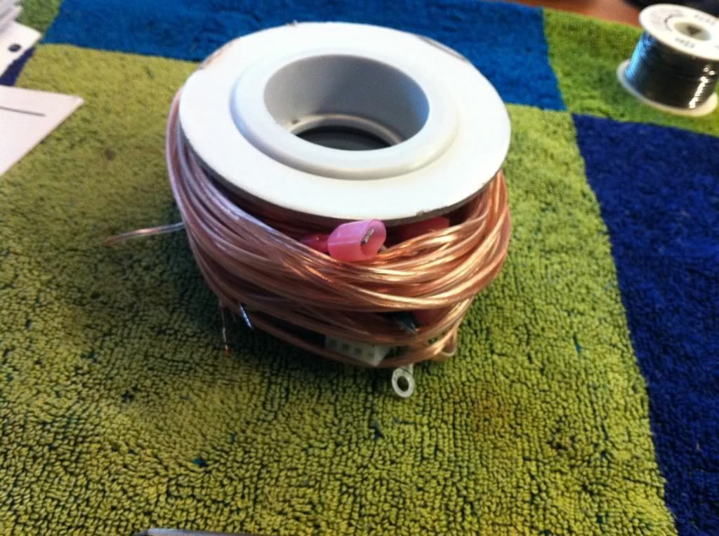 |
|
|
|
« Last Edit: February 15, 2011, 10:45:59 PM by fordmano »
|
Logged
|
83GS550 93XR650L TARD! 97WR250 99ValkyrieI/S Tri-tone 01YZ125(x2) 05DRZ-125
|
|
|
|
PhredValk
|
|
« Reply #141 on: February 16, 2011, 09:21:33 AM » |
|
Thanks, 5-19, Multiple user experiences make the info more reliable.
Fordmano, when you answer a question you don't hold back. The info and pix are amazing! I was worried that the lights I've seen (Princess Auto, clearance isle) might be junk because they're only $20-25, but now I'm going to buy a set. I'm pretty sure they will be fine for what I need.
And the pix on the mounting will be helpful, too. I've ordered 'Underware' from Rattlebars that come ready for this kind of application, but it may be a while before they do a run.
Thanks, and I owe you a beer if we ever meet,
Fred.
|
|
|
|
|
Logged
|
Growing old is mandatory, growing up is optional.
VRCCDS0237
|
|
|
fordmano
Member
Posts: 1457
San Jose, CA. 1999 I/S 232 miles when bought 11/05
San Jose, CA.
|
|
« Reply #142 on: February 23, 2011, 12:03:18 AM » |
|
Finally got back at it for a little bit over the last 2 days, yes 2 days for just the little bit your about to see. For some reason I have been BRAIN STUMPED over this electrical circuit stuff. I had most everything running before I started this LONG process. For some reason I just have been struggling with visualizing the layout so I had to draw out my circuits and then try and lay them out on the table and then go shopping 3 different times to get the parts I wanted to use to re-run all of my addon wiring. I was able to get 1 circuit completed today. I will try to explain, originally I had the Dealer installed Honda fog light set in the Pods, I want to keep these as is, sort of. I had the switch located on the left side pod as installed per Honda installation directions. Ok so far. Well I also had added 2 sets of lights a set of yellow aftermarket Fog lights under the air scoops on the bottom of the crash bars and a set of driving lights on the forks mounted under the lower triple tree and hung in an exposed position under the lowest part of the fairing. Each of my aftermarket set of lights had its on switch setup on a relay located under the seat. No big deal right. Well I picked up that very cool looking triple master cylinder mounted LED lit switches and A LED voltage meter that I want to install in the left POD where the Factory Fog light switch "WAS" located again really no big deal. Here is a first run of my circuit layout,,, I know I have a couple legs of my relays marked incorrectly I think? But I did not take an additional picture with that corrected but it is corrected now. (sorry for that confusion) 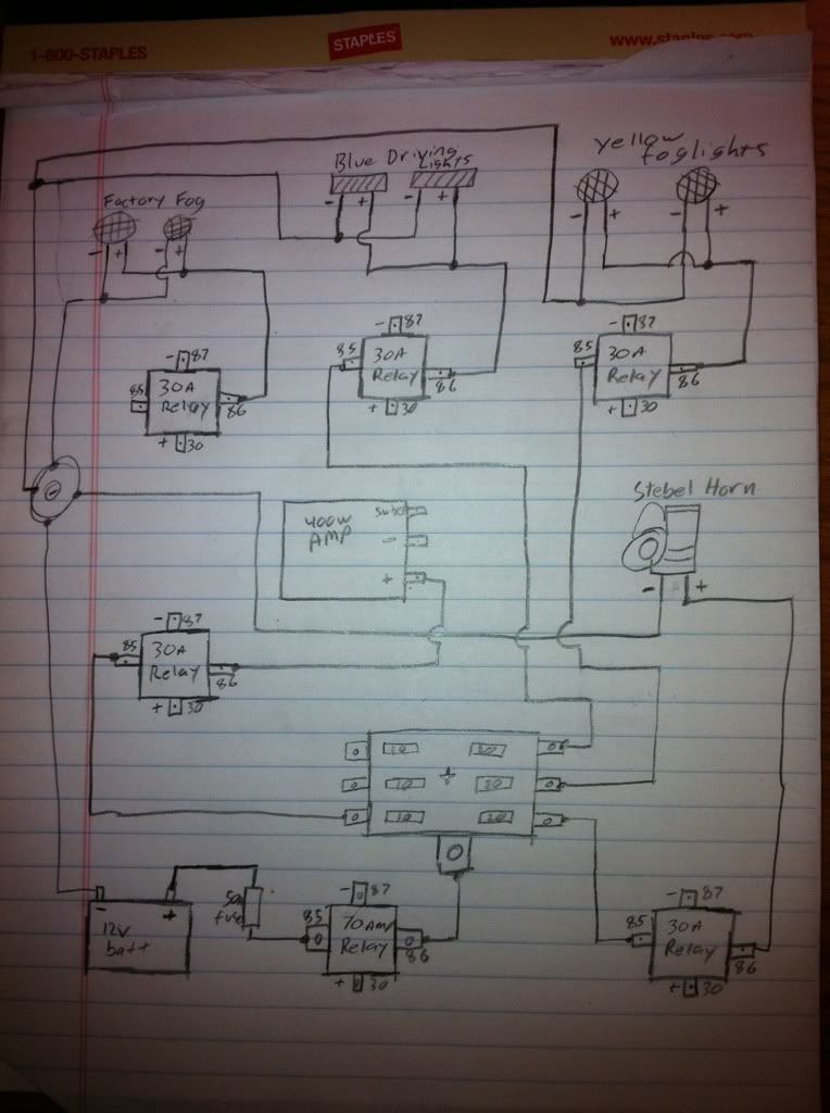 The new switch block has 5 wires 1) 12+, 1) ground- and 3) wires one of each to each switch. So instead of re-inventing the wheel with the wiring on the factory pod lights I am using the switched power that supplies the power to the + side of the Fog Light switch as my 12+ sup[ply to all 3 switches that way I do not have to run an additional 12+ power lead up to the front of the bike. To keep thing simple I also ran the Ground leg of the switch block over to the same location that the Fog lights used on the crash bar mount. Here is the Ground location. 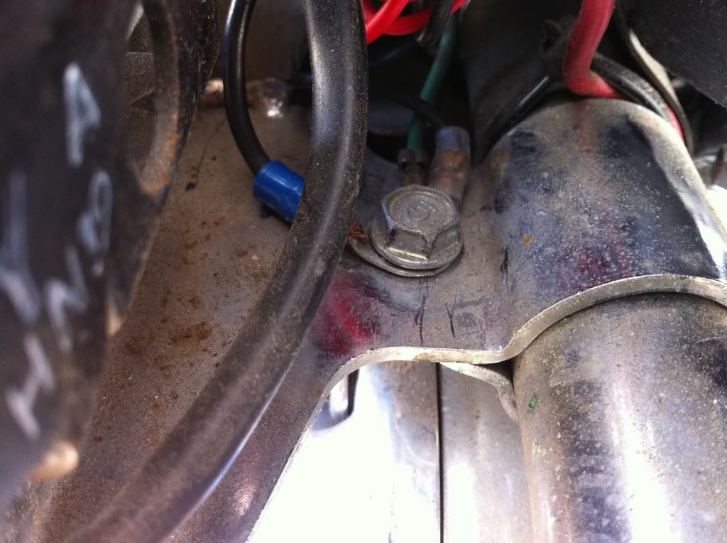 So at this point all I have completed is the (switched)12+ power supply to the bank of LED lit switches and I have gotten the factory Fog Lights back online now with the far left switch on my switch block controlling them. I used male female blade and tap connectors for this bypass of the original Fog light switch. I did remember to use dielectric grease in connections and heat shrink tubing to weather protect the connections. And a handy wrap of electrical tape to cover up the original connector from the Factor Fog Lights. You can see a few of the steps in this picture. 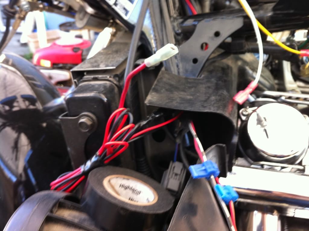 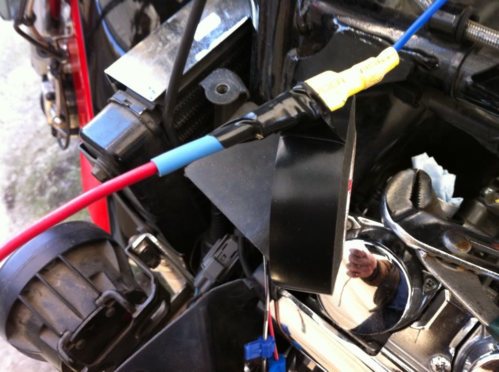 And here is the proof that the Factory Fog Lights are back online and the switch block LED lights up when placed in the ON position. 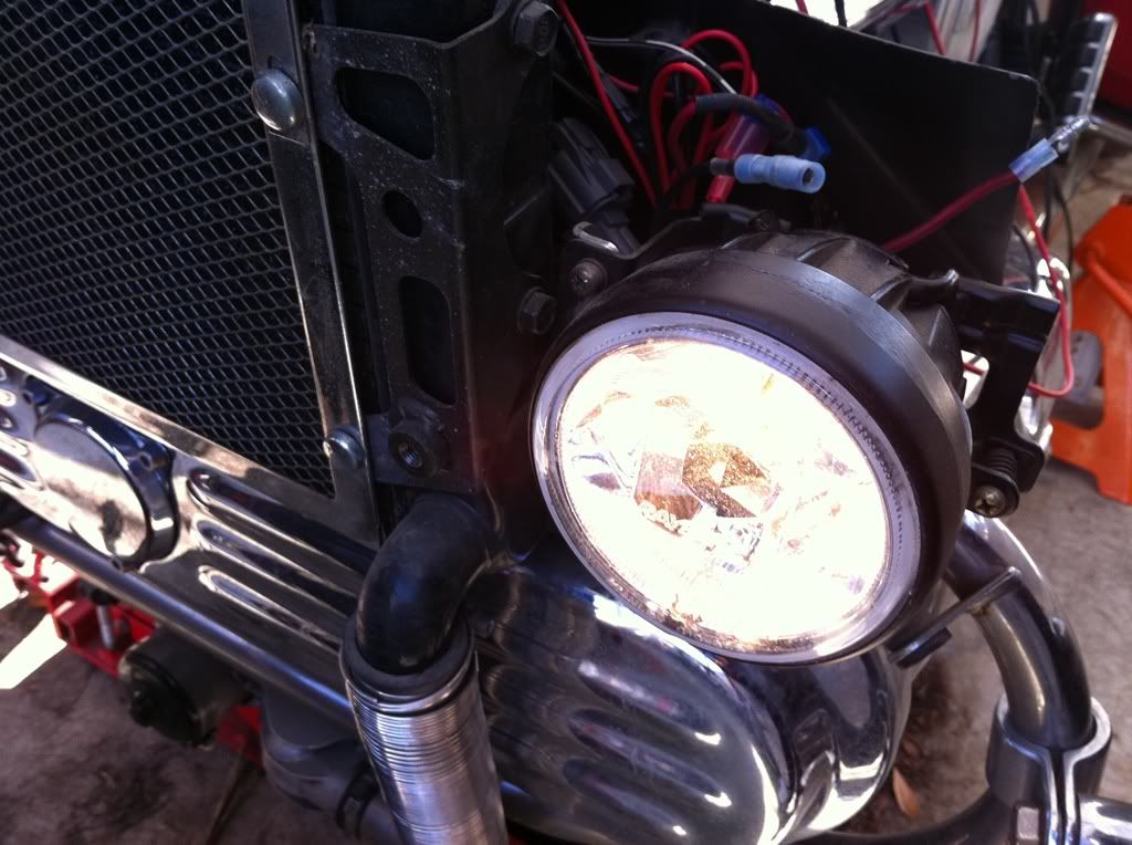 Yahoo the LED works. 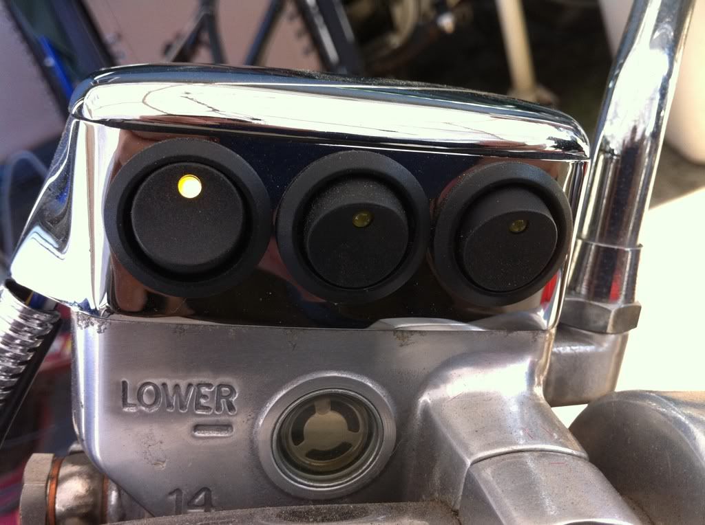 Now maybe I am back on track here, I will try and wire 1 circuit each day this week and finish up the week with getting my tank back on. The goal is to get everything from the Head bearings back buttoned up by the middle of next week. That will include Installing and wiring the Dan Marc electric fuel shut off valve, run the wiring for the Amplifier and speakers just not mounting the Amp till after this is all done. Get the Relays mounted for each of my other circuits and run the couple wires needed for the other 2 sets of lights up front. I just remembered that I still need to install/run the wiring for the cruise control before I mount the tank back into place. WHAT ELSE? I am about tuckered out with all of this. Be back soon with another set of pictures and try to explain them best I can. |
|
|
|
« Last Edit: February 23, 2011, 12:06:08 AM by fordmano »
|
Logged
|
83GS550 93XR650L TARD! 97WR250 99ValkyrieI/S Tri-tone 01YZ125(x2) 05DRZ-125
|
|
|
fordmano
Member
Posts: 1457
San Jose, CA. 1999 I/S 232 miles when bought 11/05
San Jose, CA.
|
|
« Reply #143 on: March 04, 2011, 02:02:22 AM » |
|
Finally some progress, it has been a very tough last couple of weeks as many of you know. I thank you for your patience with me and this LONG list of projects. So I have been focused on the wiring portions of this list, I have managed to get the stock factory fog lights back in working order and now I have gotten my AUX fuse block built and actually installed. I already showed the functioning master cylinder mounted switch block well I managed to get all the switches working. Here is a HooRahh picture proving there is voltage at the switches. 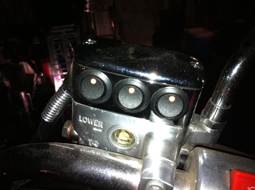 Yep they all light up and I can actually hear the relays trip when the switches are flipped on and off. So let’s back up just a little bit and I will try and share the best pictures and the biggest forward movement steps in creating the AUX fuse/Power block. You can see here that I decided to go with setting up 5 relays well actually 4 relay controlled circuits and a master relay to control the AUX fuse block itself. 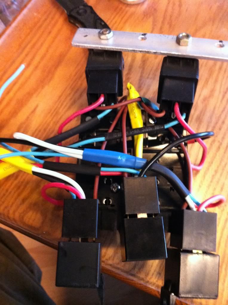 I wanted a fairly compact power block with all my relays and fuses in one simple place and be able to swap any part out on the road with minimal tools if needed but I also need to keep it all contained in a single or simple package, so I decided to attach all the relays sockets to the fuse block itself well the limited surface area on eth bottom of the fuse block required I attach the relay sockets together and I figured it would be cool to make the connecting surface clear so you could see the wires and the under side of the relay sockets. So I cut up a CD jewel case and finished it off to size of the socket layout. I used plenty of Crazy glue and some clamps to hold the relay sockets to the bottom of the fuse block. I then glued the clear square sheet of plastic I cut out to the bottom of the relays sockets and this tied them all together. 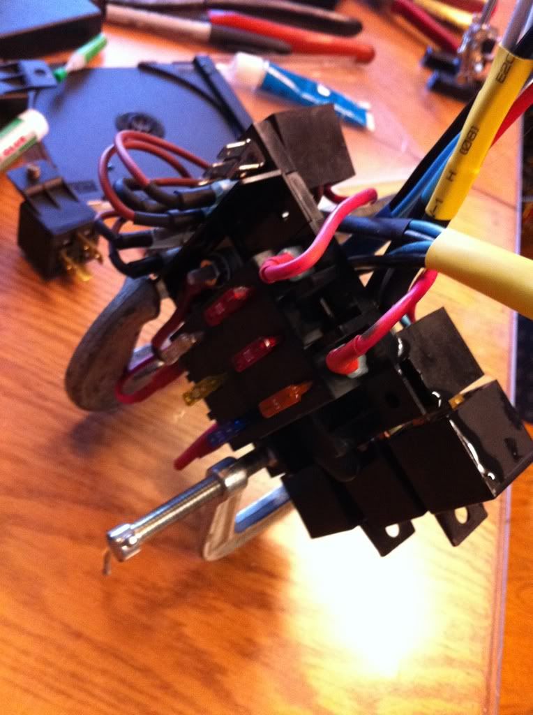 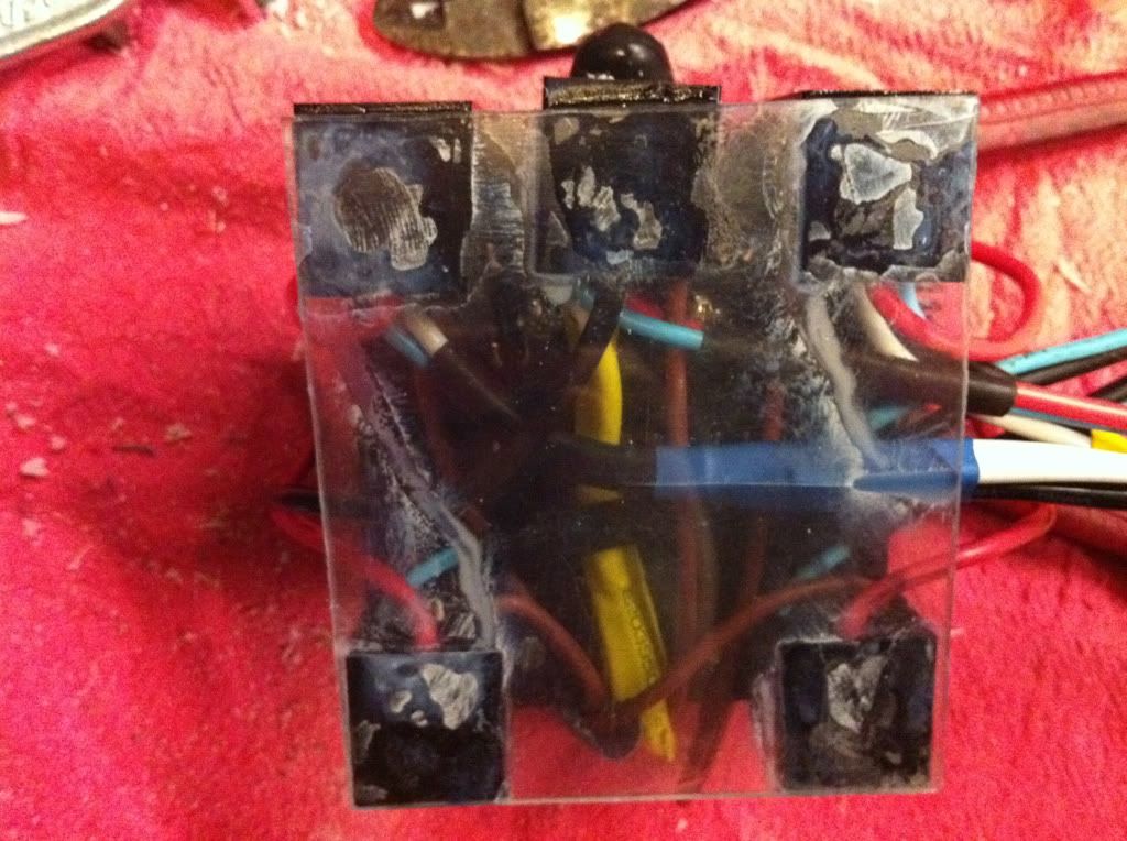 I know it’s not as pretty as I planned but it does what I wanted it to do ties the relays together and the relay sockets to the bottom of my AUX fuse block., and you can see all the wiring under there. 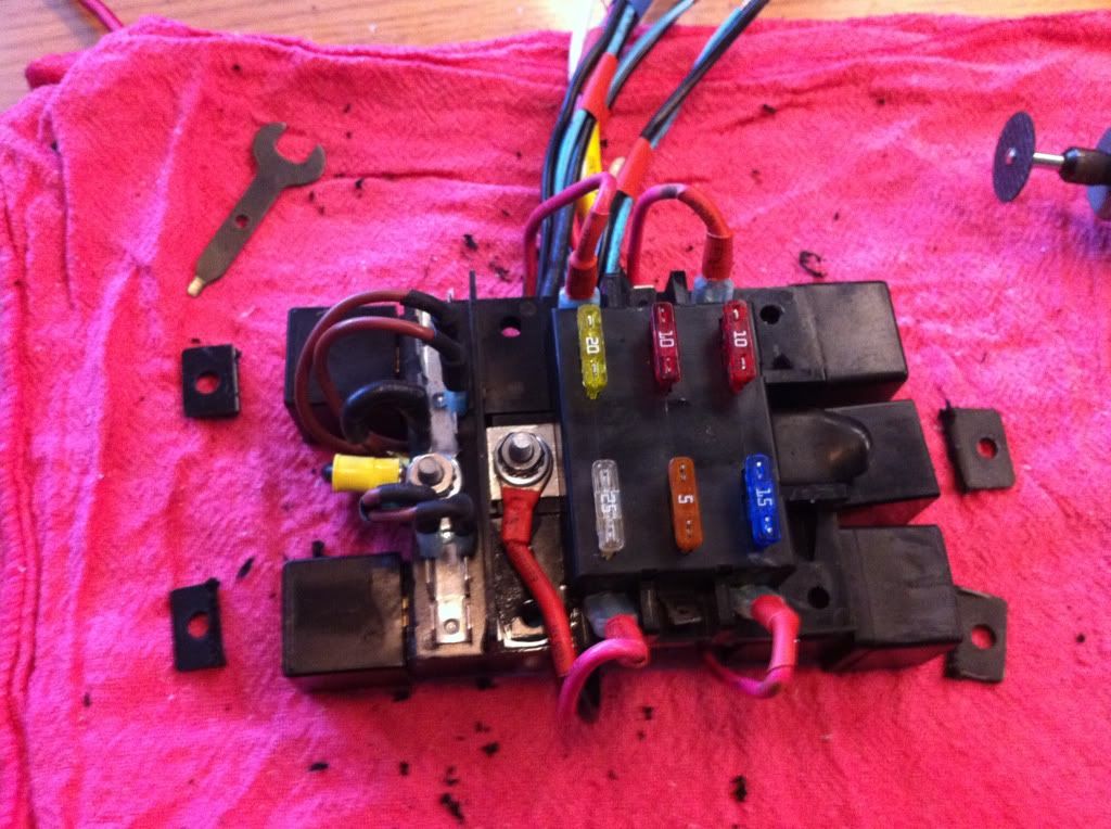 I then realized that with the relays installed with the mounting tabs on them they will not fit very easily in the compartment behind the battery so I had to do some trimming. |
|
|
|
« Last Edit: March 04, 2011, 02:54:03 AM by fordmano »
|
Logged
|
83GS550 93XR650L TARD! 97WR250 99ValkyrieI/S Tri-tone 01YZ125(x2) 05DRZ-125
|
|
|
fordmano
Member
Posts: 1457
San Jose, CA. 1999 I/S 232 miles when bought 11/05
San Jose, CA.
|
|
« Reply #144 on: March 04, 2011, 02:32:14 AM » |
|
So now to try installing it in the tray behind the battery,,,, 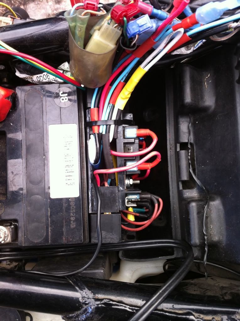 Here is one of the first test fits after getting the AUXfuse block finished (almost) this is actually after I trimmed the mounting brackets off each relay. Here is the finished direction of the installed Fuse block, I had to change out a couple of the female connectors on the lower side of the fuse block it allowed me to get the block to fit lower in this compartment I changed from straight connectors to 90degree connectors. I soldered as many connectors as I could get my soldering iron into I also used Dielectric grease on all connections to help prevent any corrosion issues later. 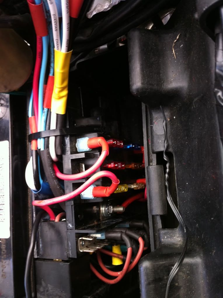 And here is the final fitting of the Fuse block, I will need to trim a section on the right hand side of the battery compartment to allow all these damn wires to run through and not interfere with the stereo housing mounting (thing) that sits on top of the battery. I figure I will just trim it down a bit and push the wire bundle down and maybe use a Zip tie to hold the bundle down and in place this will also make the factory wiring fit nicer and I still have to deal with the speaker wiring for the Amplifier install. 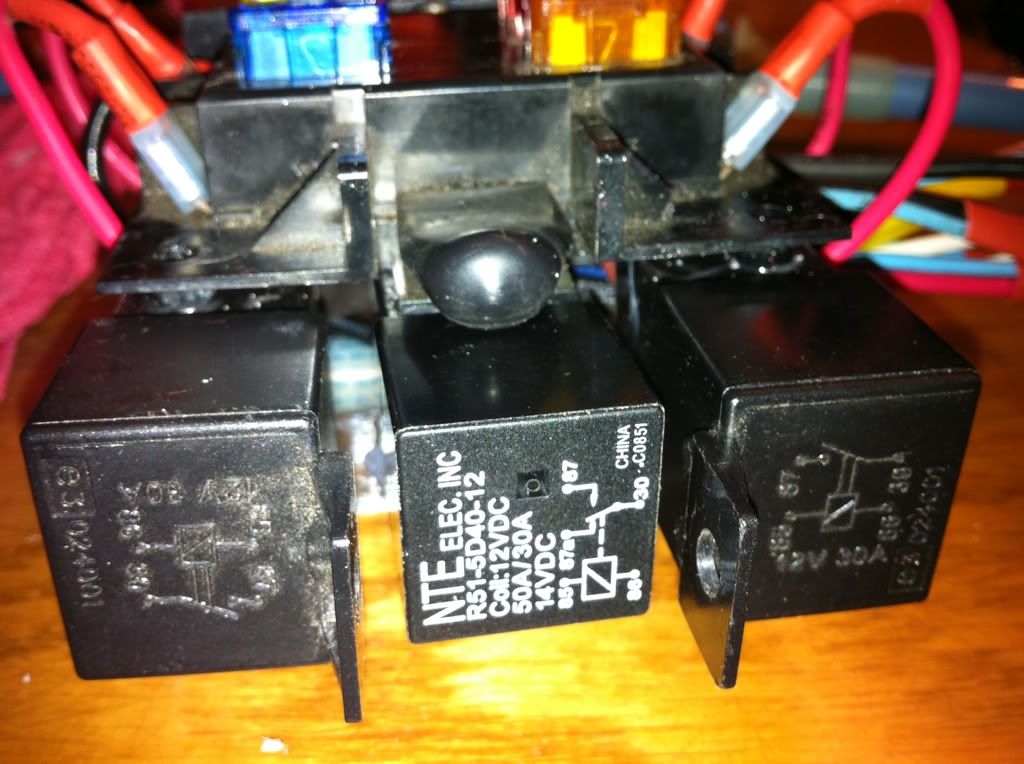 I went with a 50 amp relay as a master on/off switch, I picked up the keyed 12volt source from the extra connection under the right side cover that Honda was kind enough to leave available for us. the other 4 relays are just 30Amp units, I only when with a 40amp master fuse to the master relay, I might up that to 45A or even a 50A fuse. I used a 2Amp fuse on the keyed 12volt wire that feeds the master relay (only when the key is turned on). 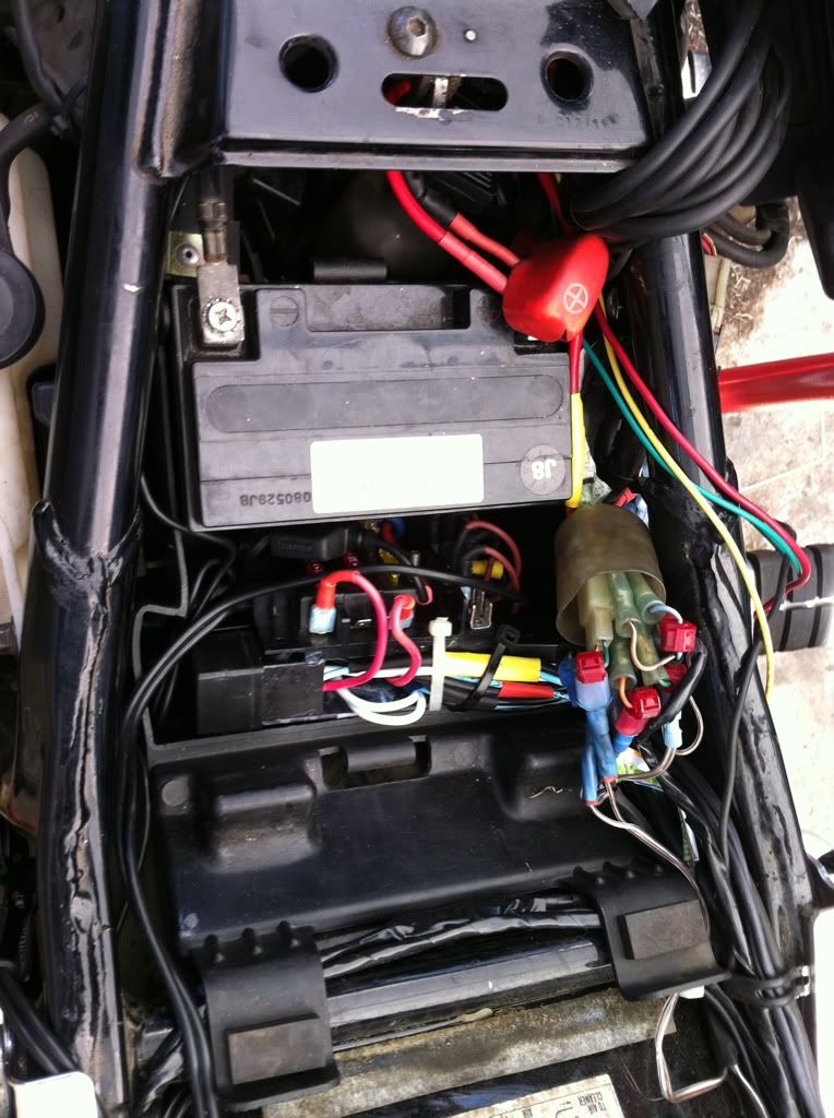 You can see I cleaned up the wiring attached to the battery terminals I moved my attachment wires for the Battery tender to the fuse block since there is a constant 12volt direct to the battery available at the fuse block this also powers the Master relay. I left enough extra wire length as to be able to pull the entire AUX fuse /Power block out completely if needed at any time. I still need to move another wire off of the positive side of my battery this will allow the radio also to sit in a more correct fashion. 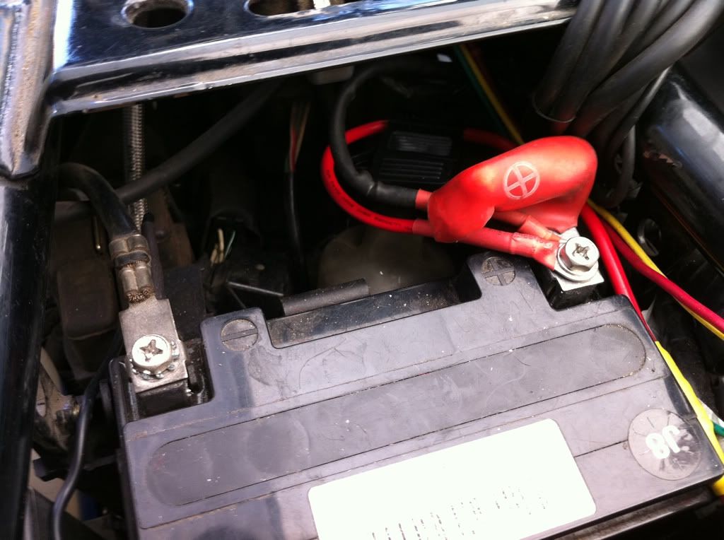 |
|
|
|
« Last Edit: March 04, 2011, 02:54:27 AM by fordmano »
|
Logged
|
83GS550 93XR650L TARD! 97WR250 99ValkyrieI/S Tri-tone 01YZ125(x2) 05DRZ-125
|
|
|
fordmano
Member
Posts: 1457
San Jose, CA. 1999 I/S 232 miles when bought 11/05
San Jose, CA.
|
|
« Reply #145 on: March 04, 2011, 02:42:29 AM » |
|
So let me step back a tiny bit again, I have gone with 4 relay controlled circuits and 2 constant non relay controlled 12volts connections, now they are controlled by the master keyed relay only but when the fuse block is energized then there will be 2 connections that are able to provide 12volts NON switched. 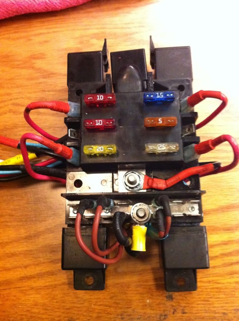 NO these fuses are not what I will be using, well the values may change according to what item ends up on each indiviual circuit. I just shoved a few fuses I had in my wiring box as an example. Now here is where I picked up my 12volt keyed source. 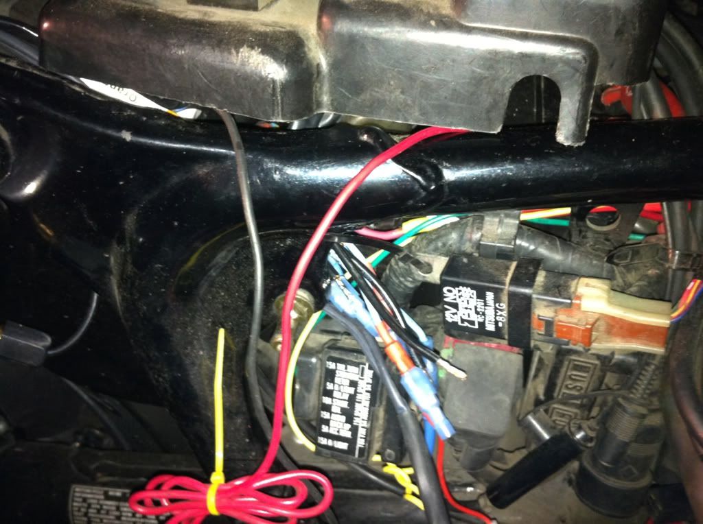 |
|
|
|
« Last Edit: March 04, 2011, 02:55:39 AM by fordmano »
|
Logged
|
83GS550 93XR650L TARD! 97WR250 99ValkyrieI/S Tri-tone 01YZ125(x2) 05DRZ-125
|
|
|
fordmano
Member
Posts: 1457
San Jose, CA. 1999 I/S 232 miles when bought 11/05
San Jose, CA.
|
|
« Reply #146 on: March 06, 2011, 03:43:33 AM » |
|
Well like most days, I did NOT get much accomplished today. So here is what was taken care of. I had to relocate just a little bit my 12volt socket, it was (and still is) located under the tank next to my Stebel air horn. Here is what it looked like before. 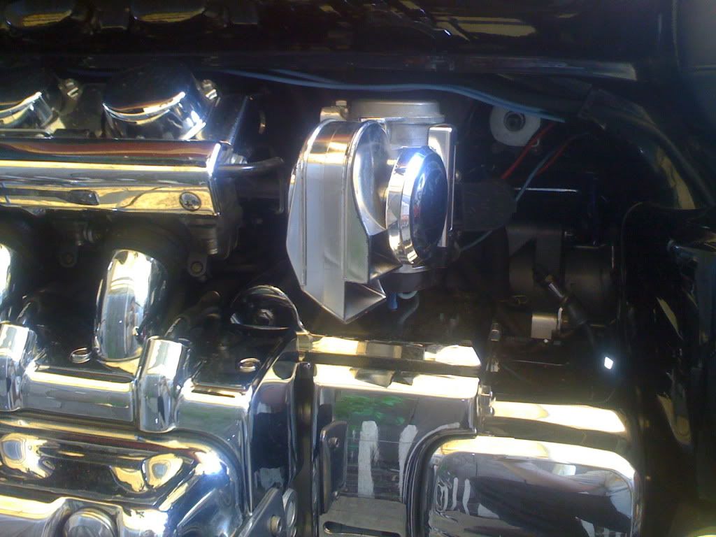 Your going to have to imagine this just a little bit here, this is exactly the mounting location of the Stebel on the next step when I re-do the wires for the stebel I found a way I like the look of better than what I had started with on this project list. 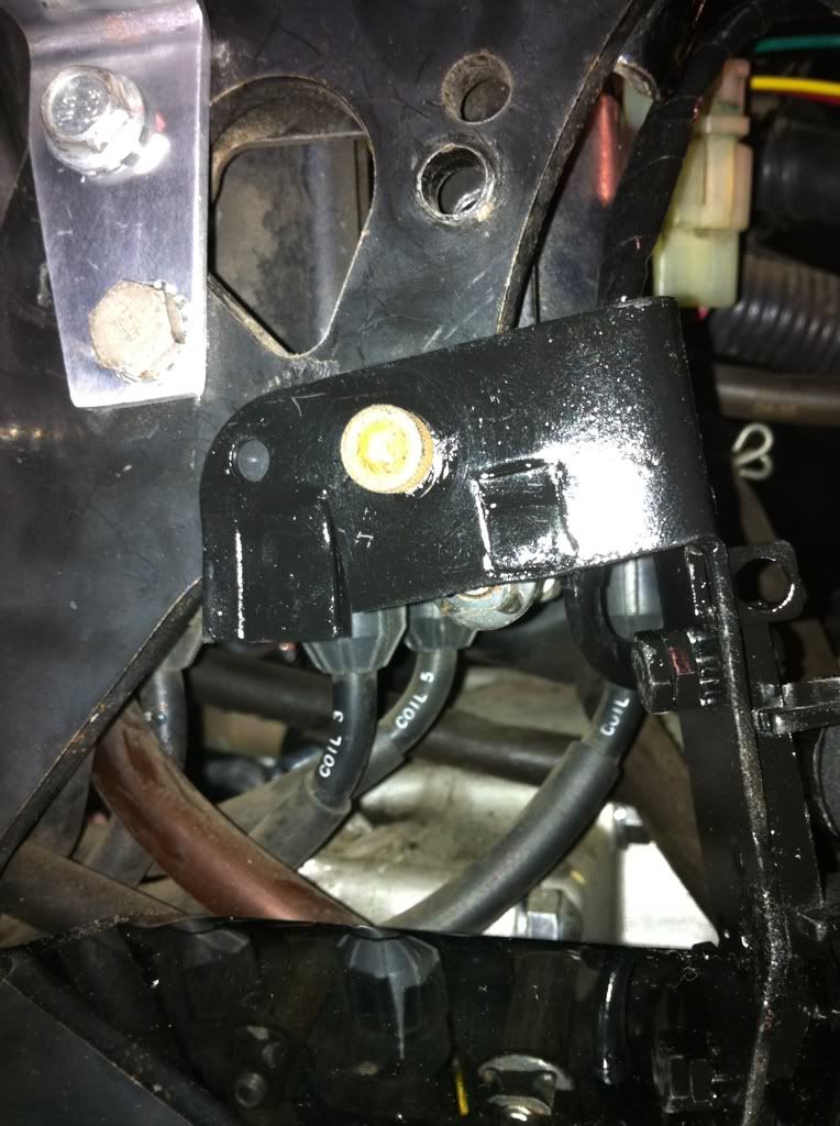 You can see the bracket for the stebel still in place. 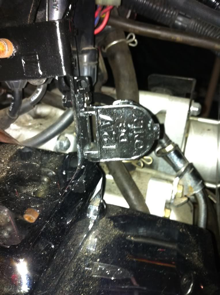 And here are a couple pictures of what I did to freshen up the 12volt weather proof socket and move it down a littel bit hidden back in a little farther and then bent the bracket to tilt it a little bit to make it a little easier to access. 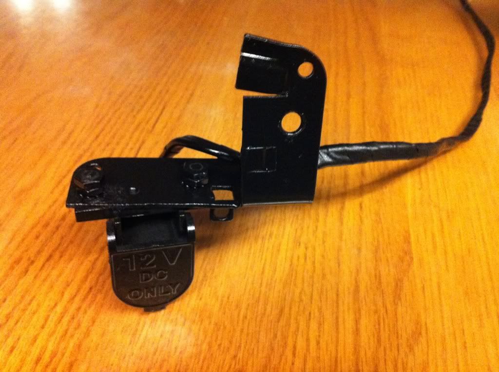 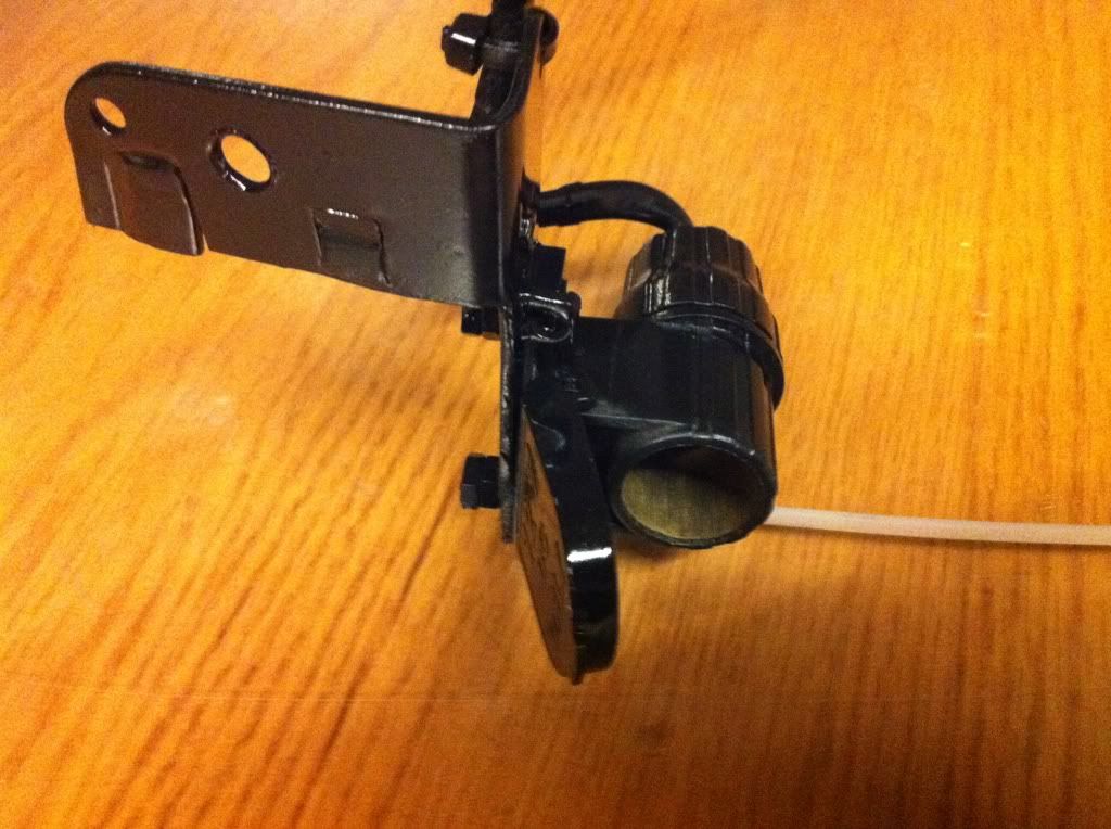 |
|
|
|
|
Logged
|
83GS550 93XR650L TARD! 97WR250 99ValkyrieI/S Tri-tone 01YZ125(x2) 05DRZ-125
|
|
|
fordmano
Member
Posts: 1457
San Jose, CA. 1999 I/S 232 miles when bought 11/05
San Jose, CA.
|
|
« Reply #147 on: March 06, 2011, 03:53:21 AM » |
|
Here are just a couple others just because I took the pictures. By the way I know the bracket looks like junk but really you will NOT be able to see it at all when it is in place and the stebel is sitting in front of it. It was just a flat square strap of black anodized steel I had laying around in the tool box. 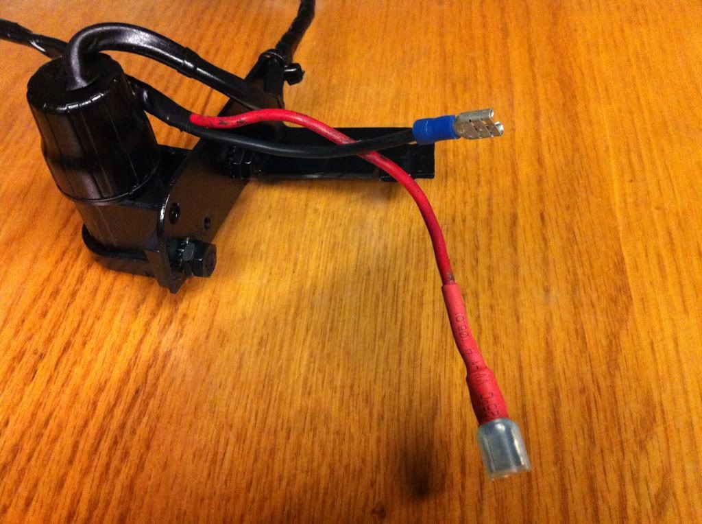 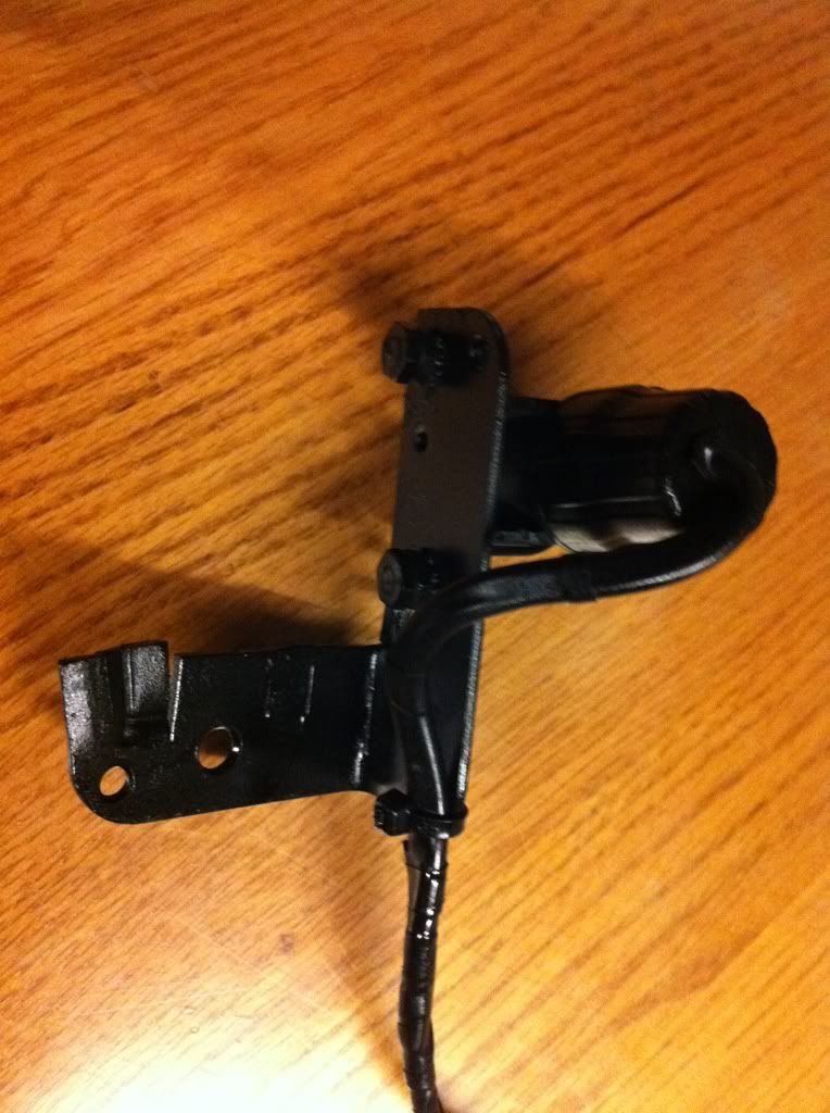 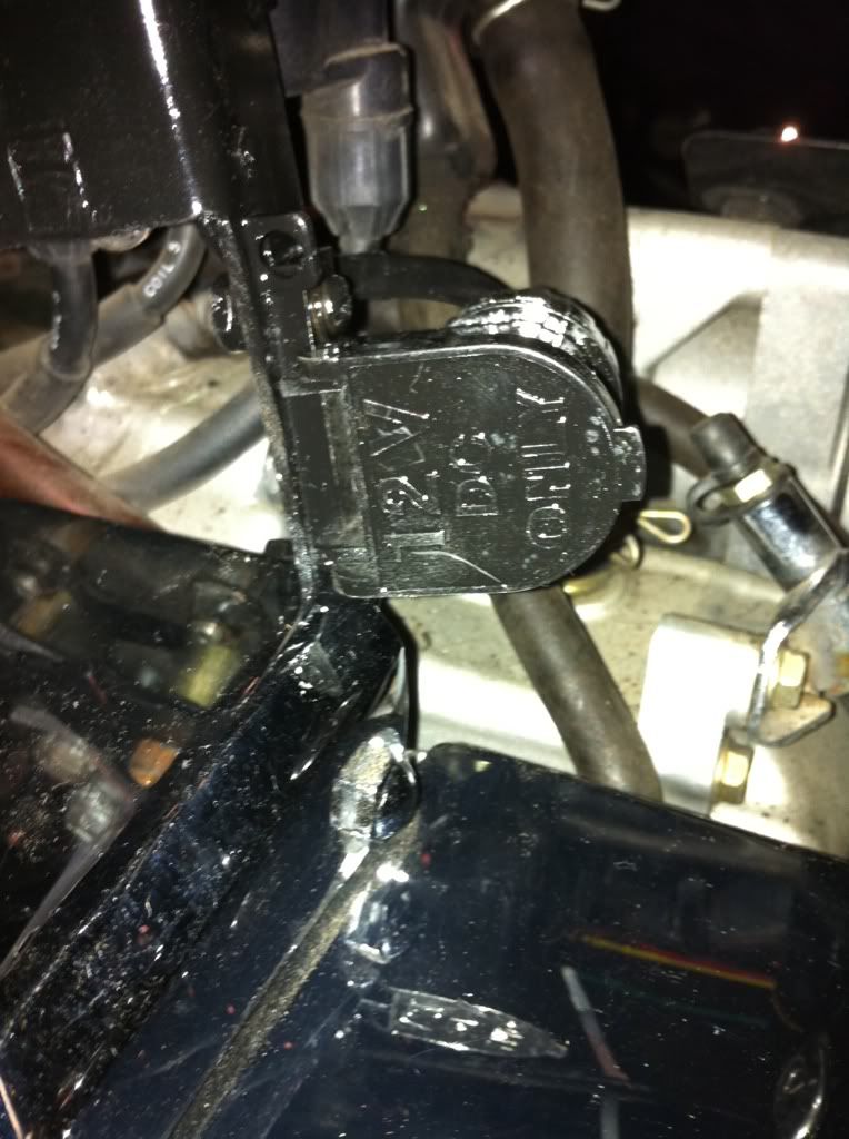 |
|
|
|
|
Logged
|
83GS550 93XR650L TARD! 97WR250 99ValkyrieI/S Tri-tone 01YZ125(x2) 05DRZ-125
|
|
|
fordmano
Member
Posts: 1457
San Jose, CA. 1999 I/S 232 miles when bought 11/05
San Jose, CA.
|
|
« Reply #148 on: March 17, 2011, 04:04:25 AM » |
|
Again I am back, I managed to finally get all my lighting wired up and working. Here is the proof that they all work now. 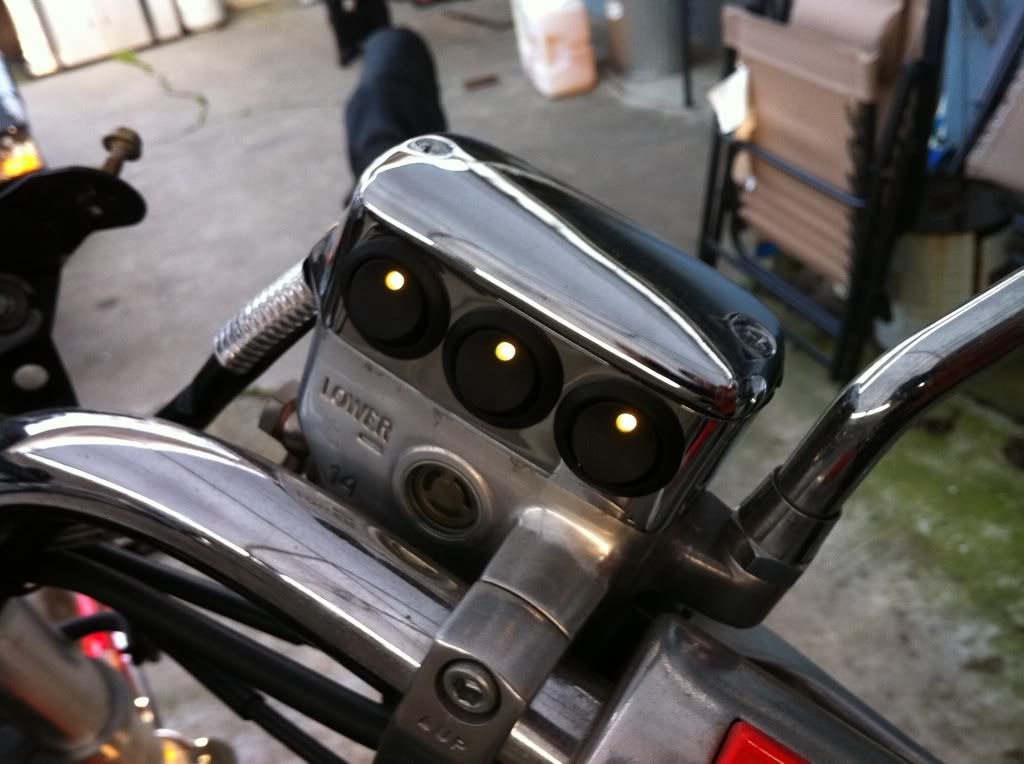 Switches all work. 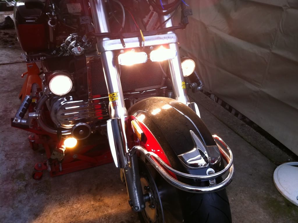 Lights all light up. 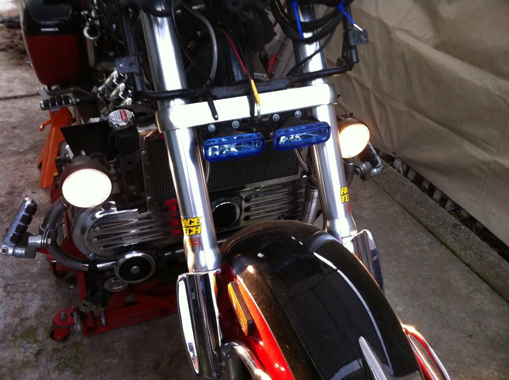 Factory fog lights work, I still need to swap out the bulb on the left hand side. I swaped it out a while before all this started with a cheap bulb from Tractor supply and it is yellow in color compaired to the PIAA bulb on the right hand side. 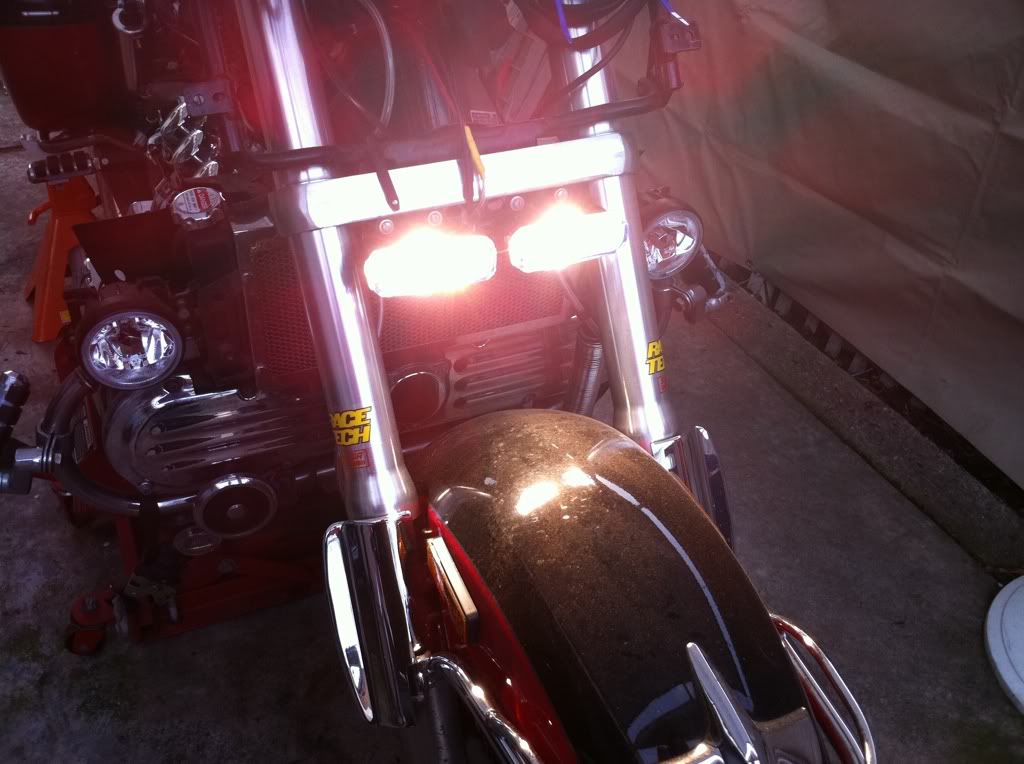 The small drivivng lights that I installed as a buckup set primarily. 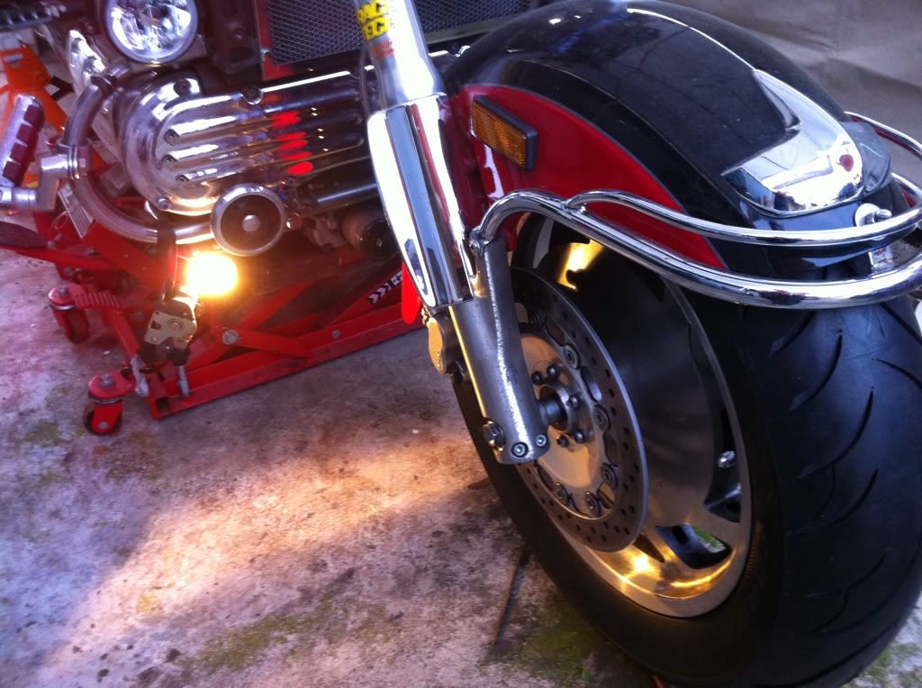 And that is my set of yellow fog lights I need to find one more for the left side I ran over something on the highway a while back and it smashed the light to smitherines. |
|
|
|
« Last Edit: March 17, 2011, 09:02:04 PM by fordmano »
|
Logged
|
83GS550 93XR650L TARD! 97WR250 99ValkyrieI/S Tri-tone 01YZ125(x2) 05DRZ-125
|
|
|
|
Cattman
|
|
« Reply #149 on: March 17, 2011, 05:39:49 AM » |
|
Just a suggestion for those lower lights. Use a p clamp and 2-3" piece of aluminim and the lights could be mounted up in front of the crash bars instead of below. As they are if the bike falls over or goes down they will be the first point of contact and be destroyed.  I've since replaced these 6" 100w spots with smaller 3" 55 watt spots. Nice work on all the electrical, mine looks like a group of wire snakes mating under the seat. |
|
|
|
|
Logged
|
|
|
|
|
Jess from VA
|
|
« Reply #150 on: March 17, 2011, 07:25:04 AM » |
|
The way to check for clearance on the lights under the guards is to slide a piece of plywood up to the (straight) front tire and lift.... if the wood hits the lights before the the outer engine guard, they will go in a tip over or fall over. And remember, they can also contact solid ground or curbs departing a gas station or other apron down to the street in a leaning turn out of a driveway. Also, depending on the watertightness of the lights you have installed, you might consider a thin bead of RTV silicone under the lens edges. The rap on the cheaper lights on motorcycles has always been weather/water.
Thanks for sharing your work with pics and discussion... appreciated.
|
|
|
|
« Last Edit: March 17, 2011, 07:27:58 AM by Jess from VA »
|
Logged
|
|
|
|
Valker
Member
Posts: 3061
Wahoo!!!!
Texas Panhandle
|
|
« Reply #151 on: March 17, 2011, 08:15:25 AM » |
|
And be careful with the ones mounted over the front fender. I have seen several people with lights mounted there that when they hit a larger bump, the lights dented the fender.
|
|
|
|
|
Logged
|
I ride a motorcycle because nothing transports me as quickly from where I am to who I am.
|
|
|
fordmano
Member
Posts: 1457
San Jose, CA. 1999 I/S 232 miles when bought 11/05
San Jose, CA.
|
|
« Reply #152 on: March 17, 2011, 04:55:38 PM » |
|
Those are all good bits of information, thanks guys. Both sets the yellow fogs and the blue/white driving lights under the fairing have been in these locations for better part of 15k-18k miles without any incident until I got pinched in my lane on the highway and was forced to make the choice of GO DOWN or risk it and run over that large black plastic bag of unknown contents, well I choose the bag figured I knew how bad it would hurt to just take the tumble against the chance of it just being an empty garbage bag. Well it was not empty, I have no clue what was in it but it was hard enough to completly crush the left side light fixture under the air scoop on the left side, no other damage at all. Scared the Hell out of me, I was rolling better than 80mph when I saw it and got down to about 55-60mph before impact. I was real carefull to make sure that there was MORE than enough clearance on those under fairing aux driving lights. I had heard about them maybe bumping the top of the fender on a full bottom out but they are really very thin and leave a good inch of clearance under a full bottom out condition. Thanks again guys and I am glad somebody is checking out my progress and I take getting some enjoyment out of my efforts even as slow as they have been. Thanks, Matt P.S. I got a couple more things done today I will share them later when I get to work and have some of that company paid free time.  |
|
|
|
« Last Edit: August 29, 2013, 11:52:14 PM by fordmano »
|
Logged
|
83GS550 93XR650L TARD! 97WR250 99ValkyrieI/S Tri-tone 01YZ125(x2) 05DRZ-125
|
|
|
fordmano
Member
Posts: 1457
San Jose, CA. 1999 I/S 232 miles when bought 11/05
San Jose, CA.
|
|
« Reply #153 on: March 17, 2011, 08:39:26 PM » |
|
Well I made it into the office, now I can take care of personal stuff.  Ok this might be a big step too you but for me it was another big step in the right direction. After thinking about how I attached my battery tender extension leads I figured out I had actually ran it to the output side of my primary relay that controls all my other relays and when the key is off there is NO path to the battery for the tender to charge anything. Well I already have 2 things attached directly to the battery and it gets tough to place the radio back on top without modifying the radio cover and it's also tough to get the battery cable screw on and off with too many things attached to the top of the post. So what to do? Well we need a remote location for mounting always hot items, so let’s build a bus bar type of thing (I know that is not the correct name for it but I understand what I mean). So let me show the pictures and describe what is shown after each picture. 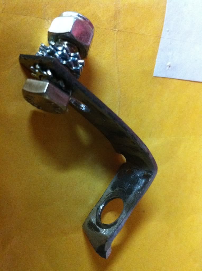 OK, I found a small scrap of steel from something that needed this little bracket to keep it's orientation so it had 2 little ears that stood up (actually down) and a almost 90 degree bend already in it lets start with that. I then drilled a couple holes at the other end to run a small bolt through and this will be where I attach any extra items that need to be always HOT.(12+volts) 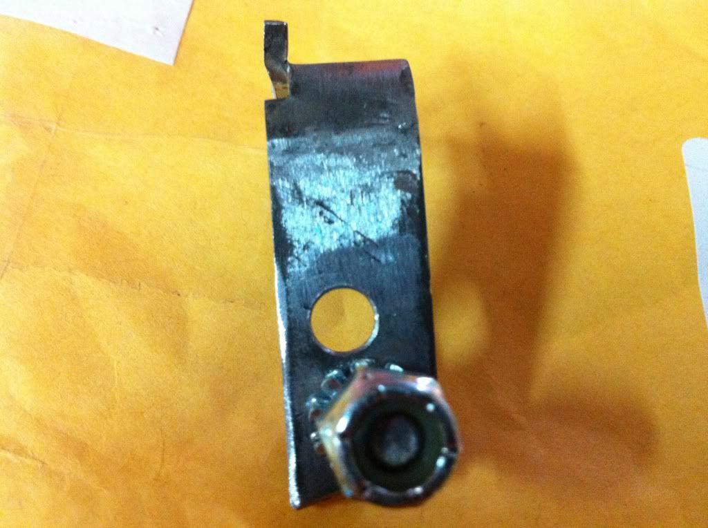 This little bracket actually had a hole large enough for the battery terminal bolt al drilled in it. But the ears that hang down on the battery cable were a bit narrow so I had to grind it down a bit. 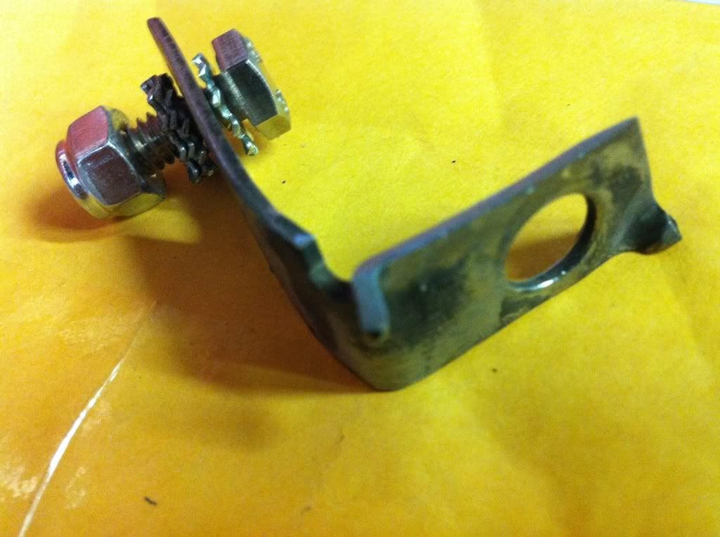 So after getting it shaped and fitted as I want now it’s time to attach the desired wires to it and insulate it as to protect it and protect anything from touching it since it will be a full +12volts and could be a bad thing if anything shorts against it. 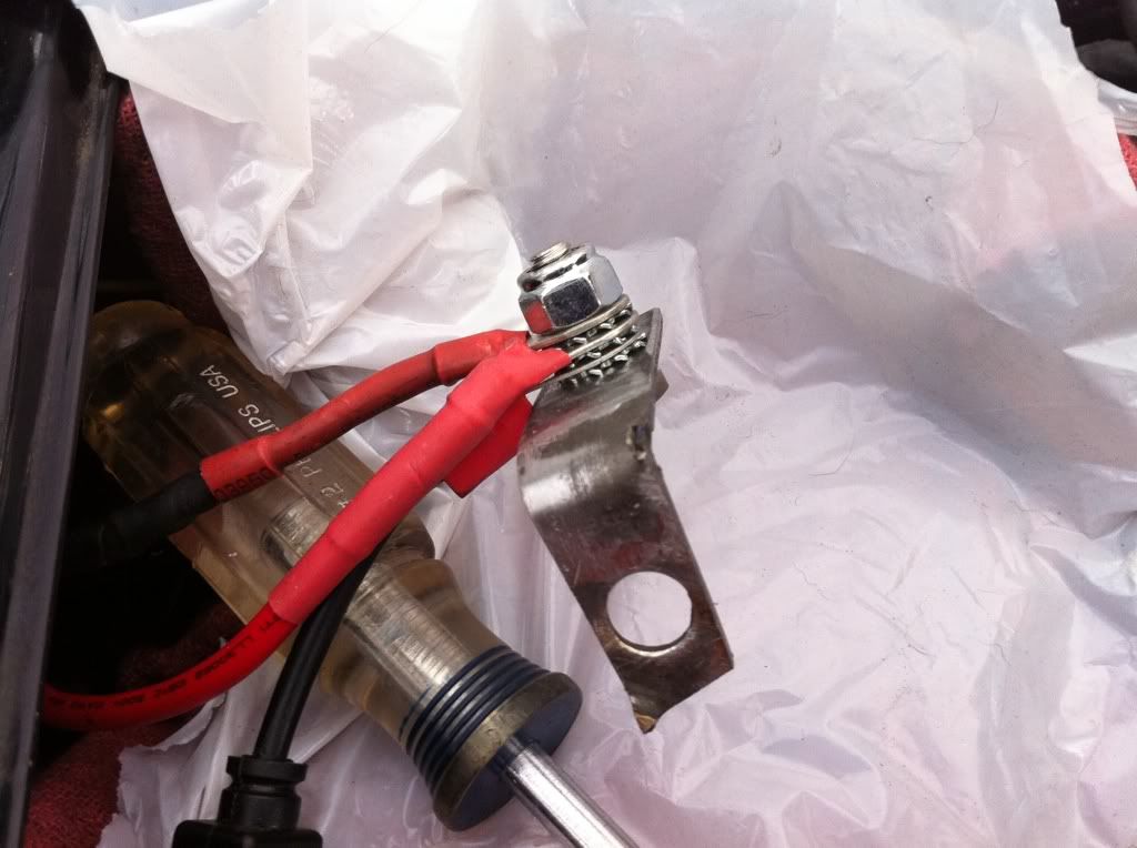 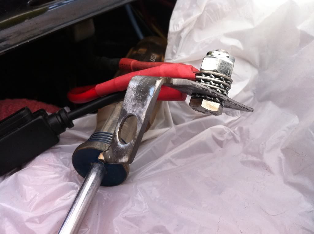 Can you see where this is headed? |
|
|
|
« Last Edit: March 17, 2011, 09:04:41 PM by fordmano »
|
Logged
|
83GS550 93XR650L TARD! 97WR250 99ValkyrieI/S Tri-tone 01YZ125(x2) 05DRZ-125
|
|
|
fordmano
Member
Posts: 1457
San Jose, CA. 1999 I/S 232 miles when bought 11/05
San Jose, CA.
|
|
« Reply #154 on: March 17, 2011, 08:43:35 PM » |
|
First coat on, now wait and give it another one in a bit. 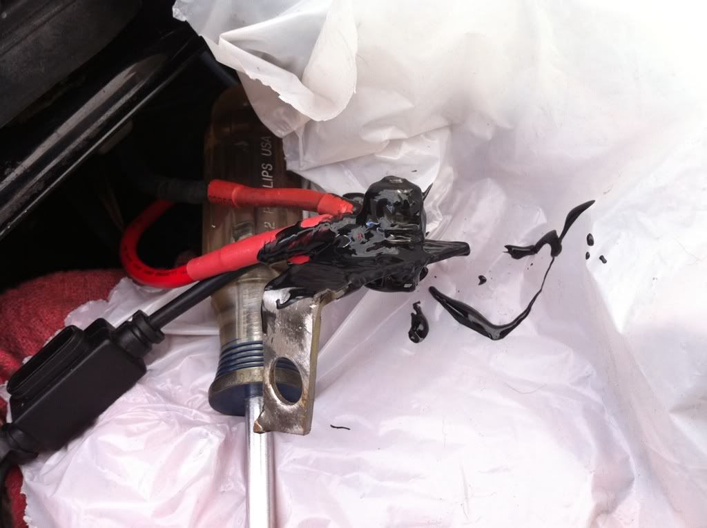 Here is what I am using to insulate this power bar. 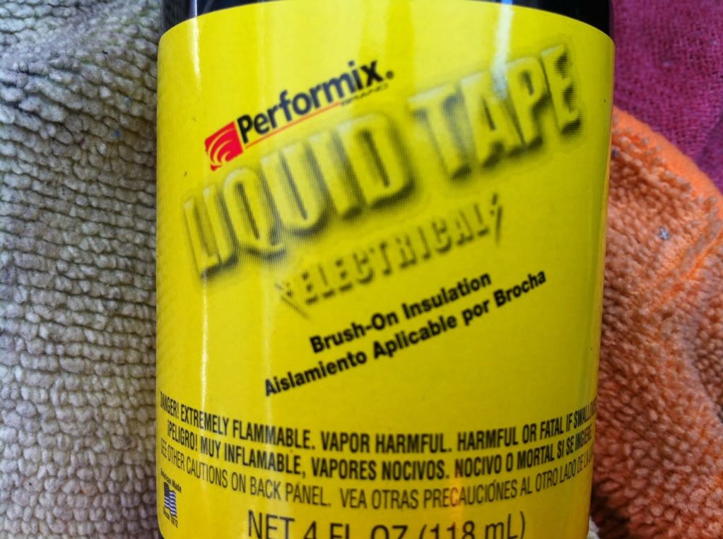 Now it’s time for another coating. 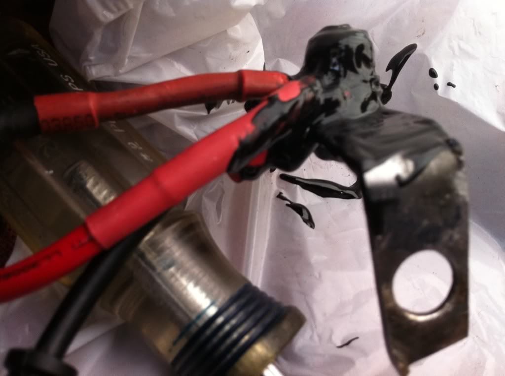 And below is how it looks installed completely. Can even see it, I am sure some or many if not most or all would or might have done this different but it’s my project,,, LOL. 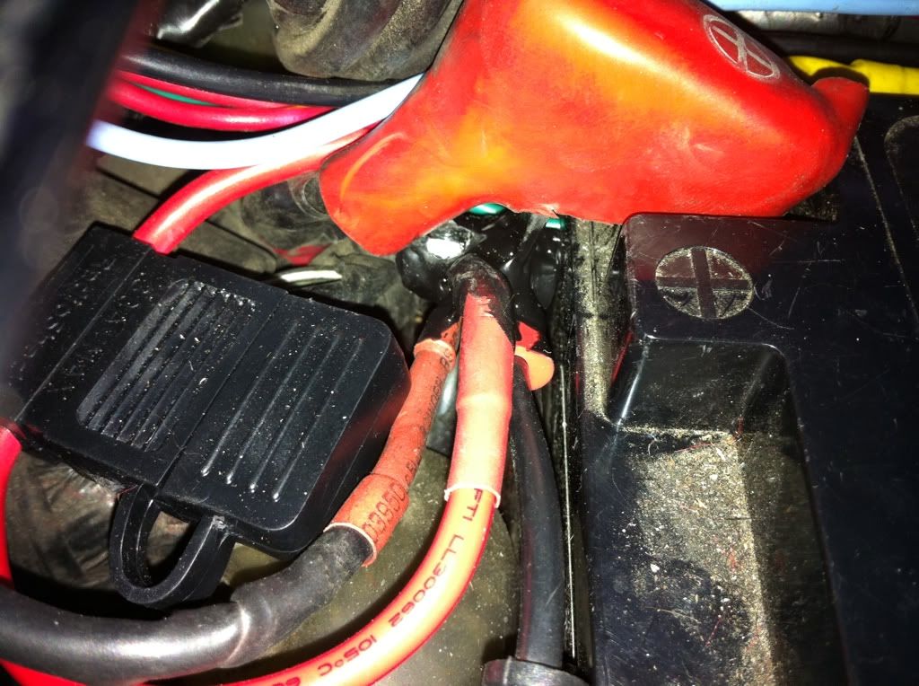 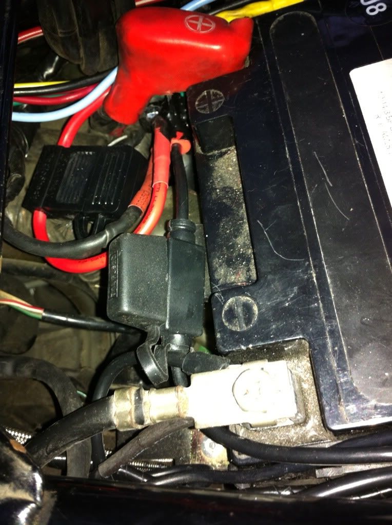 |
|
|
|
« Last Edit: March 17, 2011, 09:05:03 PM by fordmano »
|
Logged
|
83GS550 93XR650L TARD! 97WR250 99ValkyrieI/S Tri-tone 01YZ125(x2) 05DRZ-125
|
|
|
fordmano
Member
Posts: 1457
San Jose, CA. 1999 I/S 232 miles when bought 11/05
San Jose, CA.
|
|
« Reply #155 on: March 17, 2011, 09:00:27 PM » |
|
Well here is what my rats nest looks like it does tidy up a bit from this I trimmed the side panel of the battery box so these wires will run under the radio cover without too much pressure on the connections. 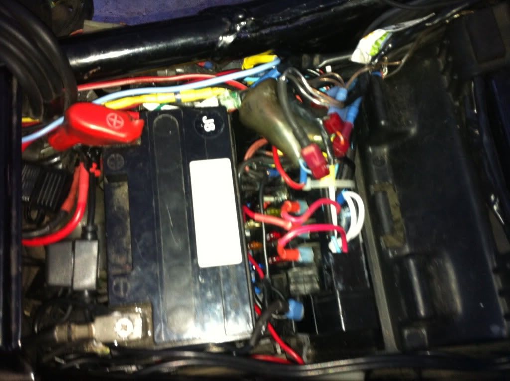 OK so now that that is done I was able to get the radio but back in and it lays down low almost even with the frame again. 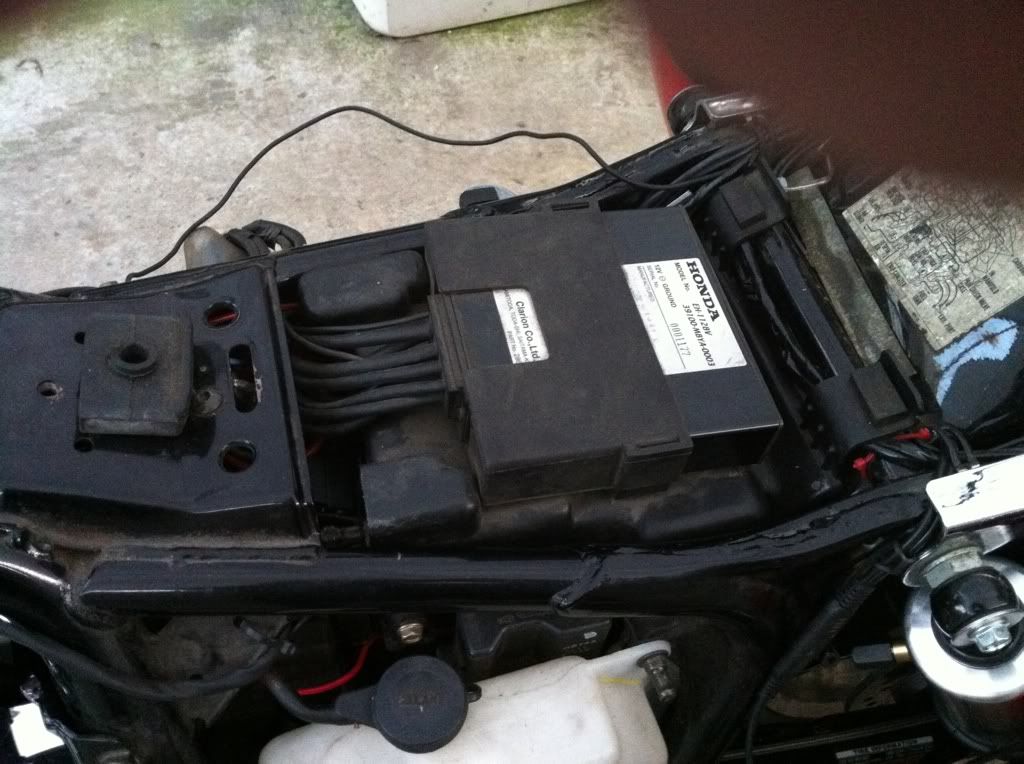 You can see in that picture above, I ran the battery tender lead back around the battery and wrapped it under the frame cross bar over the front of the rear fender. Then again back over the crossbar and under the chrome side rail that holds the trunk in place then brought it out in front of the rear shock there on the left hand side of the bike and it will sit under the flap that hangs down the side of my seat. The only other thing I finished up today was the DanMark electric fuel shut off valve. I wired it to its own fuse on my aux power/fuse block and grounded it directly to the frame. This way it will only have power when the key is in the on/run position, thus I will never have to turn my fuel valve off again manually unless I want too. I decided to strap that valve down I was worried about it flopping around and pulling the fuel line loose from the clamps on the factory fuel line section. 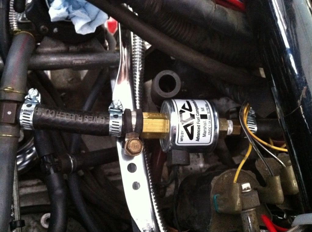 That’s about it for today, as always thanks for looking and following my projects. Be back As Soon As Possible with more pictures and explanations. |
|
|
|
« Last Edit: March 17, 2011, 09:05:45 PM by fordmano »
|
Logged
|
83GS550 93XR650L TARD! 97WR250 99ValkyrieI/S Tri-tone 01YZ125(x2) 05DRZ-125
|
|
|
fordmano
Member
Posts: 1457
San Jose, CA. 1999 I/S 232 miles when bought 11/05
San Jose, CA.
|
|
« Reply #156 on: April 01, 2011, 12:24:00 AM » |
|
Well other than running into the actually engine running properly problem I have that up in a entirely new thread, that I will add in here when I get it all figured out. I have gotten something else positive finished now after lots and lots of looking and thinking and even being offered some wonderful help from one of our VRCC brothers (He offered to create a mount for my Cruise control controls of out polished stainless) well I appreciate it greatly and if what I came up with does not work out I will bother him later and pay him for his effort if he is still willing to build me a mount when time comes. So here is what I came up with, and like usual I did not start taking pictures during the prefab efforts. What this originally was made from is one of those Chrome clamps made for the top of the cubicle walls in offices for hanging a coat hanger on it so it has square corners and a funny punched out slot in it. I figured out that if I used the vise to pull it around a 1" round file handle it will after lots of attempts it will pull nicely around and have a perfectly round section to wrap around the handle bars. So let's have some pictures to help explain what it ended up as. 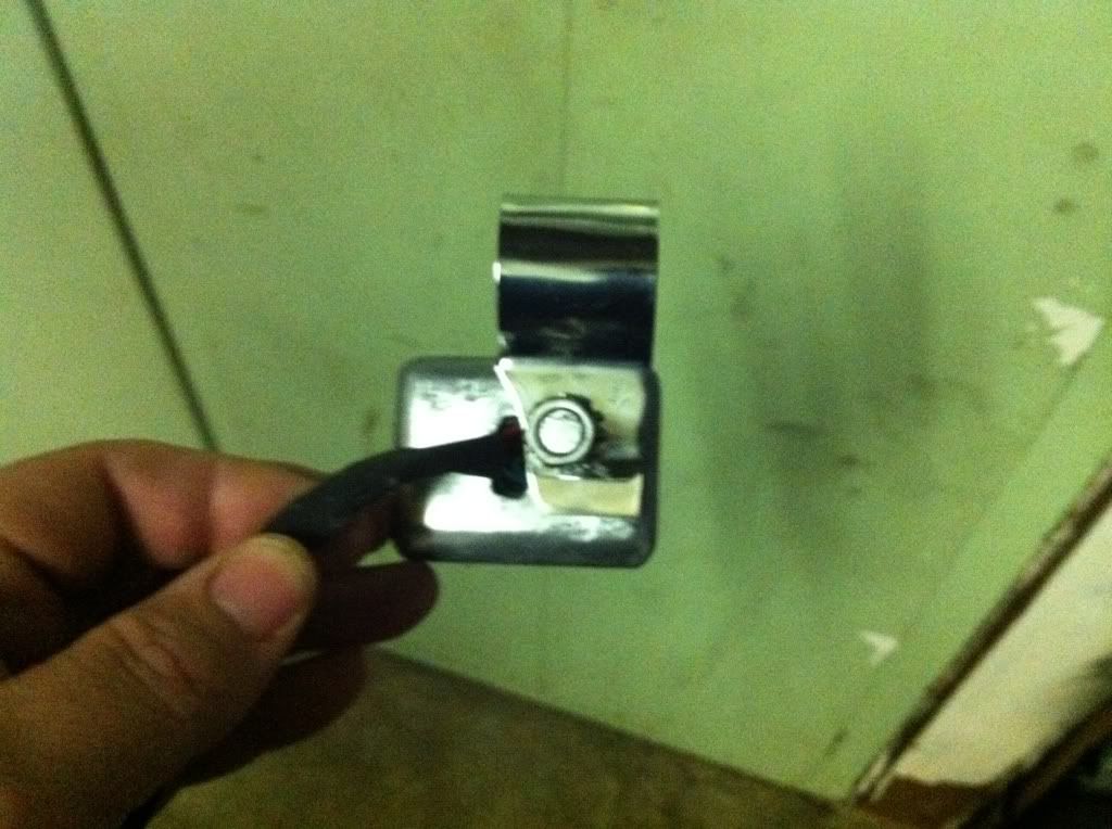 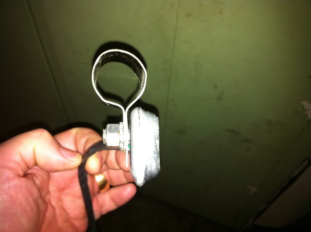 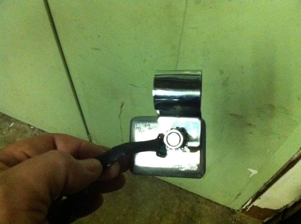 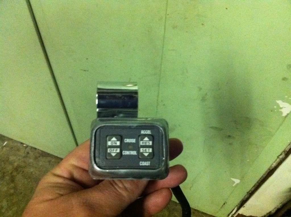 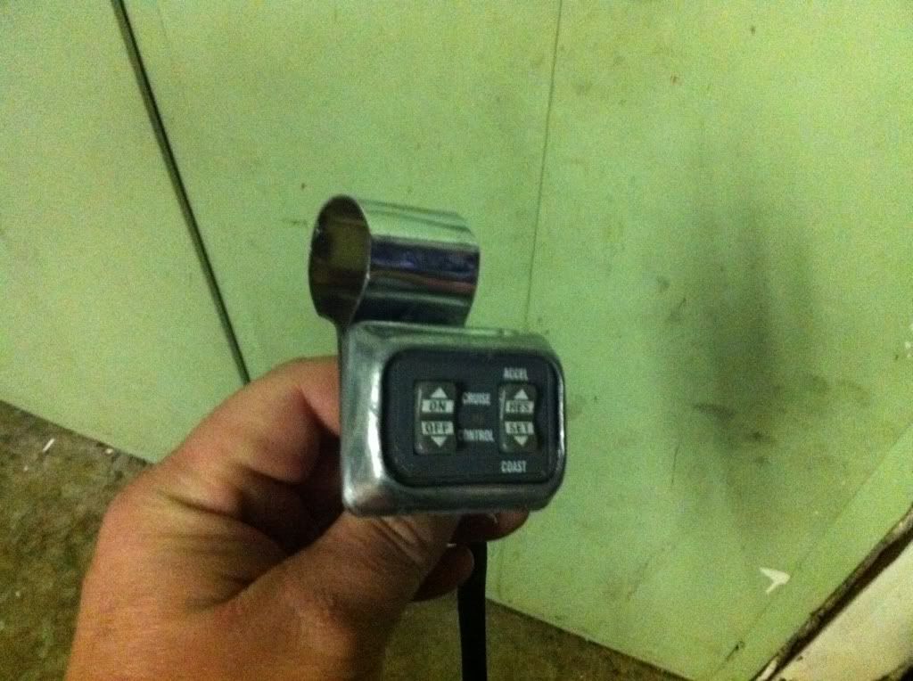 Ok so it's not perfectly round, I laid a folded red shop rag down and then laid the chrome bracket down then placed the file handle in the middle of the chrome thingy then placed it between the vice jaws and started cranking away and just slipped it a little at a time and an occasional tap with a rubber mallet until it finally was rolled nicely around the file handle.. It took probably better part of an hour to get this all done. |
|
|
|
« Last Edit: April 01, 2011, 12:43:06 AM by fordmano »
|
Logged
|
83GS550 93XR650L TARD! 97WR250 99ValkyrieI/S Tri-tone 01YZ125(x2) 05DRZ-125
|
|
|
fordmano
Member
Posts: 1457
San Jose, CA. 1999 I/S 232 miles when bought 11/05
San Jose, CA.
|
|
« Reply #157 on: April 01, 2011, 12:26:27 AM » |
|
Then I figured out it was actually too large of a diameter for the bars so I went to a bicycle shop and asked for an old inner tube from a bike and they gave me an old tube (no charge) and I started cutting sections of it until I got the correct size to wrap around the handle bars and then place my mount over it. 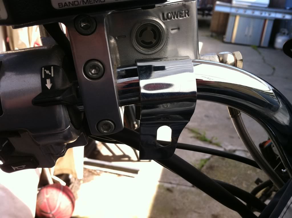 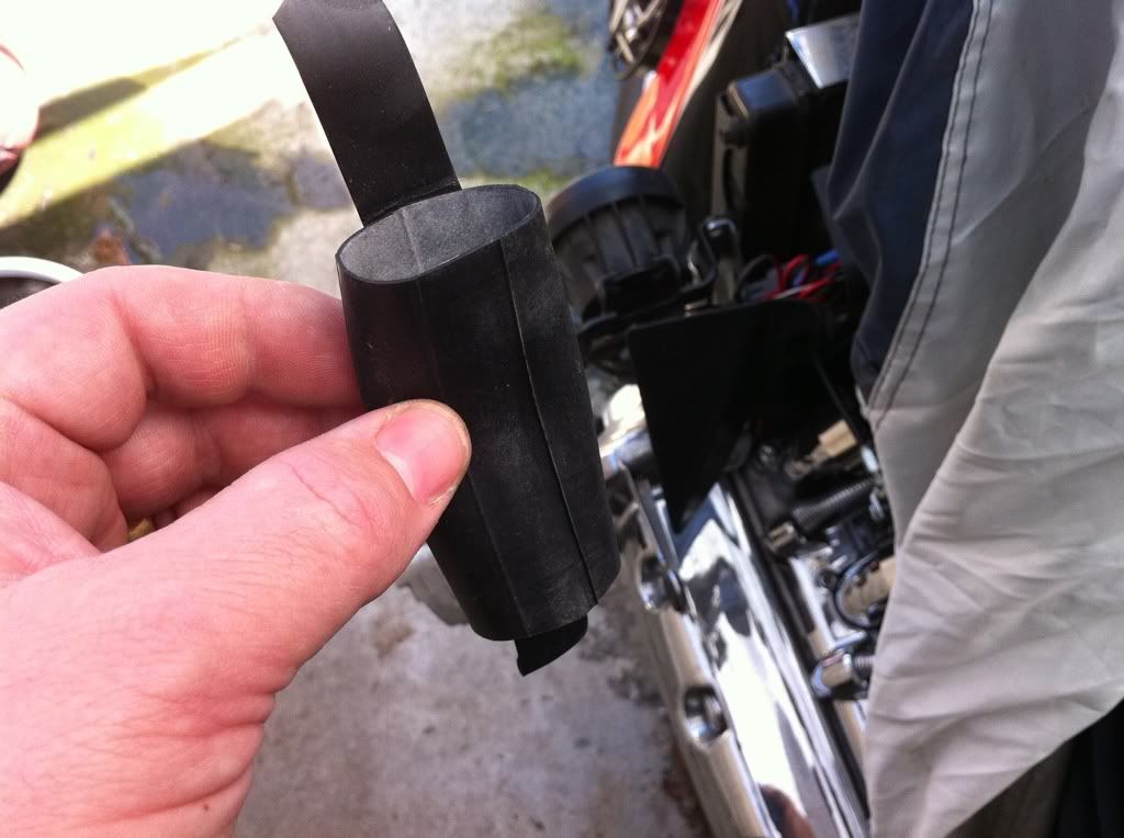 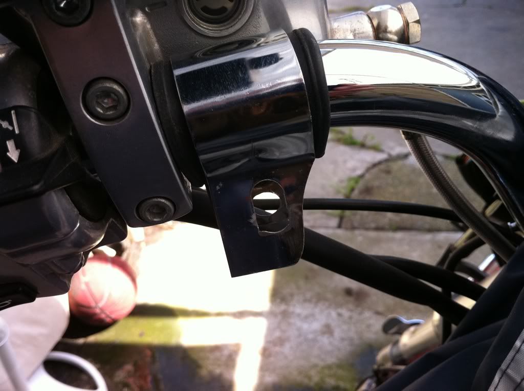 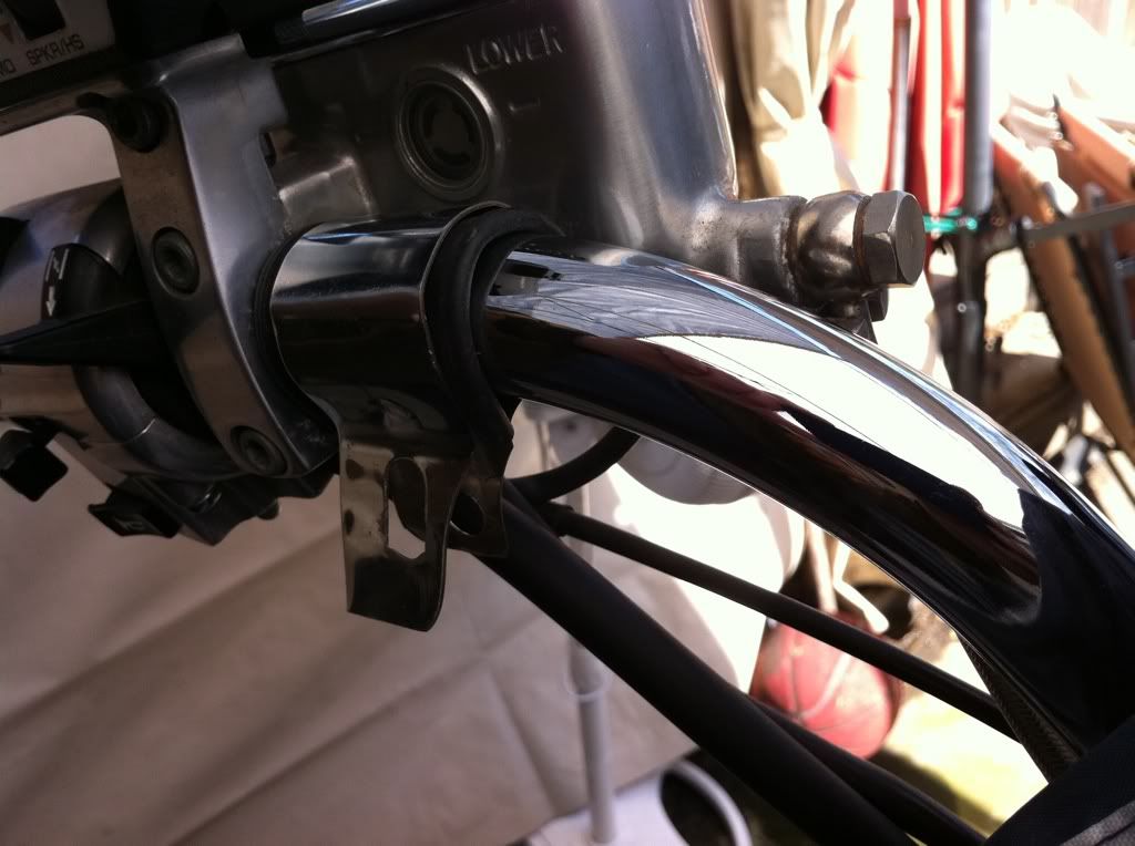 Now you get the idea I am sure. Nice looking and out of the way but still easily reachable, I did not want to cover up anything else and I also wanted to be able to hide and protect the wires as best I could. |
|
|
|
« Last Edit: April 01, 2011, 12:43:58 AM by fordmano »
|
Logged
|
83GS550 93XR650L TARD! 97WR250 99ValkyrieI/S Tri-tone 01YZ125(x2) 05DRZ-125
|
|
|
fordmano
Member
Posts: 1457
San Jose, CA. 1999 I/S 232 miles when bought 11/05
San Jose, CA.
|
|
« Reply #158 on: April 01, 2011, 12:31:59 AM » |
|
So here is the almost final product. I like it a lot, well it’s cool for not having proper tools or work area or time. 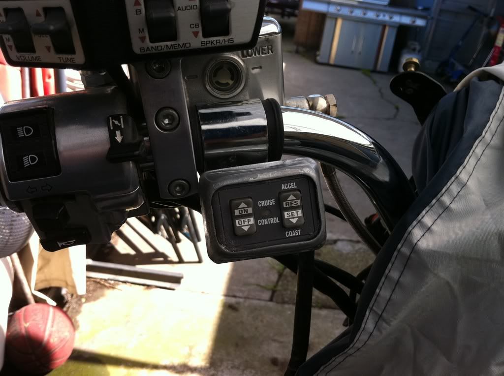 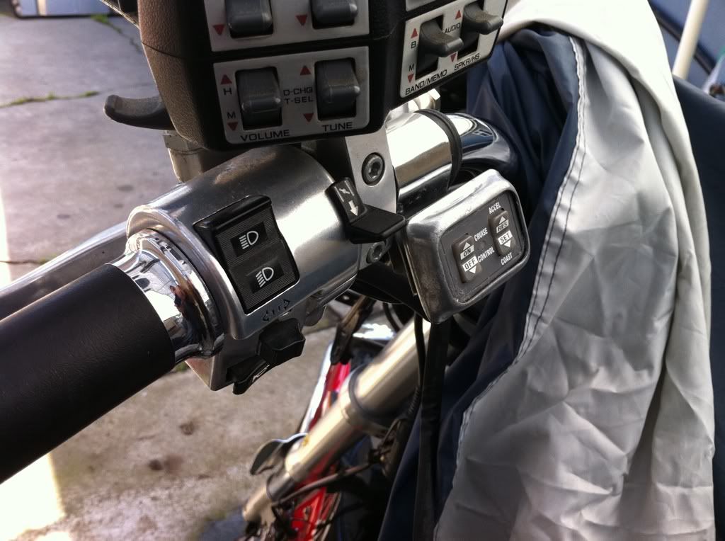 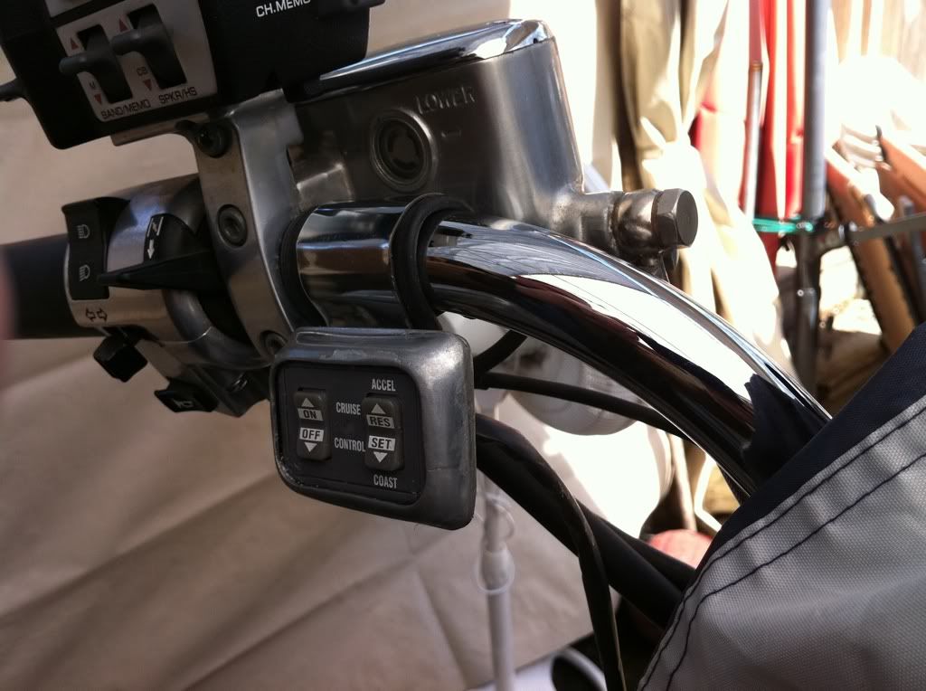 I just keep chugging along with all of this, I wish I had more time and a better work area. 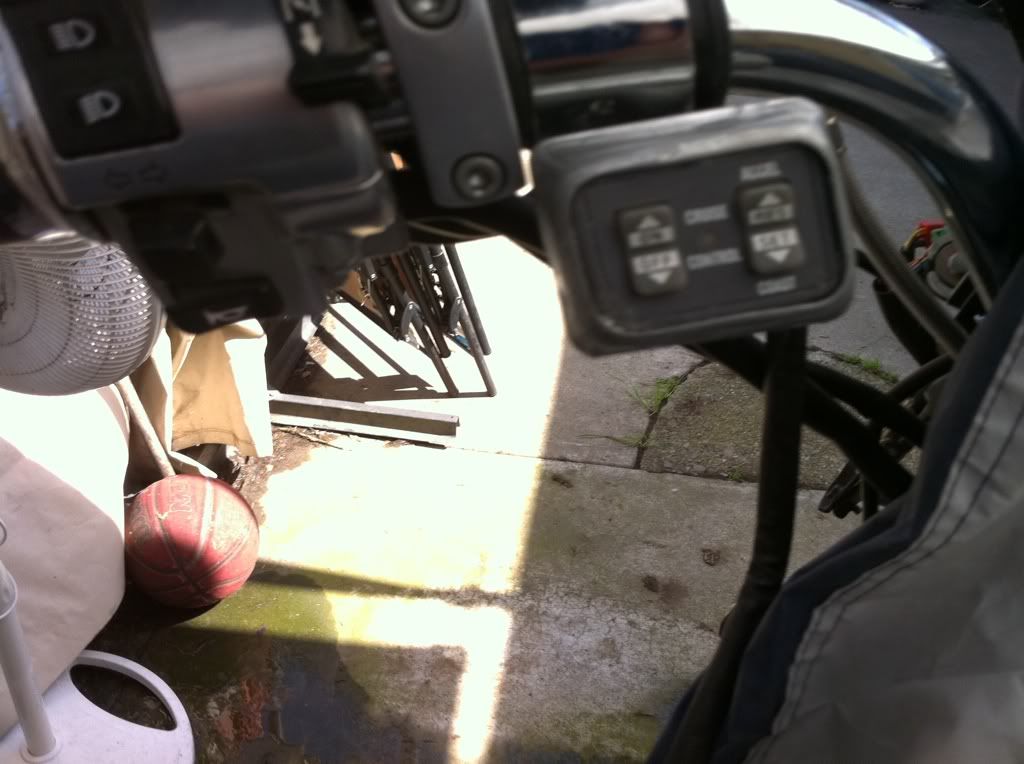 I do have a little bit more touch up work to do with this mount, I will be adding a small bead of silicone around the front and also around the sides to help make sure it is weather proof as best it can be. |
|
|
|
« Last Edit: August 29, 2013, 11:54:02 PM by fordmano »
|
Logged
|
83GS550 93XR650L TARD! 97WR250 99ValkyrieI/S Tri-tone 01YZ125(x2) 05DRZ-125
|
|
|
fordmano
Member
Posts: 1457
San Jose, CA. 1999 I/S 232 miles when bought 11/05
San Jose, CA.
|
|
« Reply #159 on: April 01, 2011, 10:28:10 PM » |
|
I know these 2 pictures look the same as the last few but,, I found a few moments between dealing with my Carburation issue to tighten up the mount for my Cruise Control bracket. Looks good, fairly easy to reach only time will tell for sure if this location works well enough for me but it is solid and easy to see. 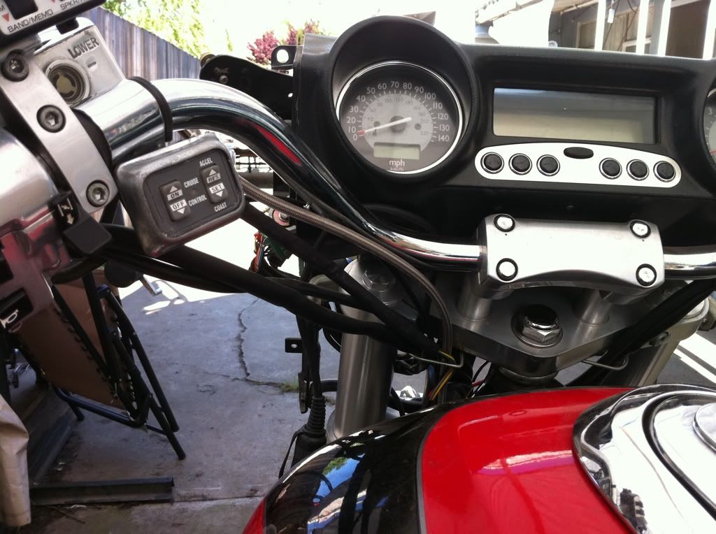 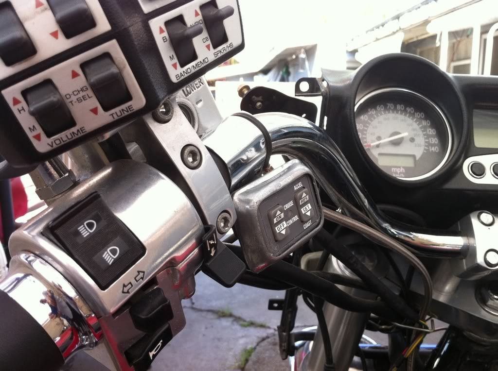 I might see if I can twist it around a little bit more so it faces me a little more straight on. Not sure if there is enough material to allow for any movement on a rotation direction. |
|
|
|
« Last Edit: April 01, 2011, 10:36:35 PM by fordmano »
|
Logged
|
83GS550 93XR650L TARD! 97WR250 99ValkyrieI/S Tri-tone 01YZ125(x2) 05DRZ-125
|
|
|
|


