gordonv
Member
    
Posts: 5766
VRCC # 31419
Richmond BC
|
 |
« on: August 13, 2017, 03:00:17 PM » |
|
Like our buddy fordmano, who posted a Multipoint upgrade thread ( http://www.valkyrieforum.com/bbs/index.php/topic,21439.0.html) , of all the changes to his bike, I thought this would be a good idea for myself too, rather than a few little how-to posts. I'm not a good writer, but I hope I wont loose too many, and make it interesting enough to follow along with me, and to also show some how-to do these projects. My wife Tess was away for the day yesterday, and I had nothing planed, so figured it was a good time to get off my ass and start on my long list of items I had planed for my IS to personalize it more to my liking. 1st on the list, 4" truck stacks, based upon the how-to in Shop Talk. http://www.valkyrieriders.com/shoptalk/truckstackinstall.htmI started the early morning off, with a drive south of the border to pick up my replacement center cover. Back home to pick up my mc trailer. Then over to mom's garage to pick up my exhaust from my previous green/silver IS, which I had intended on fixing the piggies, but never did. Then over to work, where I could us the shop space after hours to work on my mc, as long as I was cleaned up for the next day and not in the way at work. We have strata bylaws at home about not working on vehicles on property, and as a council member, I sort of need to abide by those bylaws. 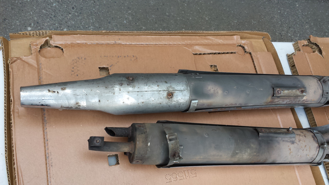 My removed pipes, from when I posted last year about getting a deal on a pair of NOS OEM std/tourer pipes out of a Seattle Good Will store. You can see where the clamps have already broken, I got one end stack off by the 8mm bolts breaking, and the other is waiting to see if the penetrating fluid and heat will help me get it off without breaking those bolts. 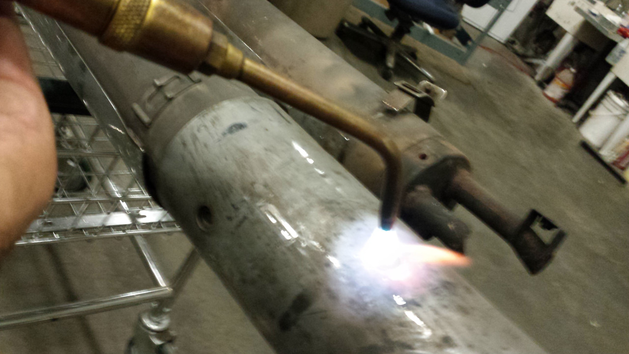 The chrome stack heated up a lot faster than that little bolt, so I removed the heat and tried the socket, and proceeded to break the bolt head right off. Just like the rest of them. Luckily for me, I wasn't going to need to worry about them (drill them out and re-thread) since I was replacing the whole thing with 4" slash cut truck stacks. No longer using the original end pieces. After the end piece, there was the clamps holding the shroud onto the mufflers. Again, heat, but this time no worry of the chrome, and off they came. Since I was there, I also removed the forward covers from the pipes. A good time to get those bolts loose, and put them back on with some anti seize for future removal. Then I got the 4" grinder out, and time to clean up the mufflers, so they will accept the truck stacks. I started with one exhaust, cut the piggies off, all the way back to the top of the weld. Then onto the muffler. No hammer/chisel, so started by grinding the spot weld off for the end clips. Didn't really work to well, so screw driver and pliers. Bent and worried it off. Then started using the edge of the grinding wheel to remove any high points, exposed welds and the like. It seems the cut off wheel I was using, isn't very strong for this work, and chipped away very easily. It did the job, but when I moved over to the 2nd exhaust, the cut off wheel was a little short now to cut right through the piggy, and I had to come from multiple sides, and was also nicking the other exhaust holes. Then the end clip. It was easier to cut it through the middle, and using the pliers, worried it off the muffler. Then again, grinding down all the high spots. 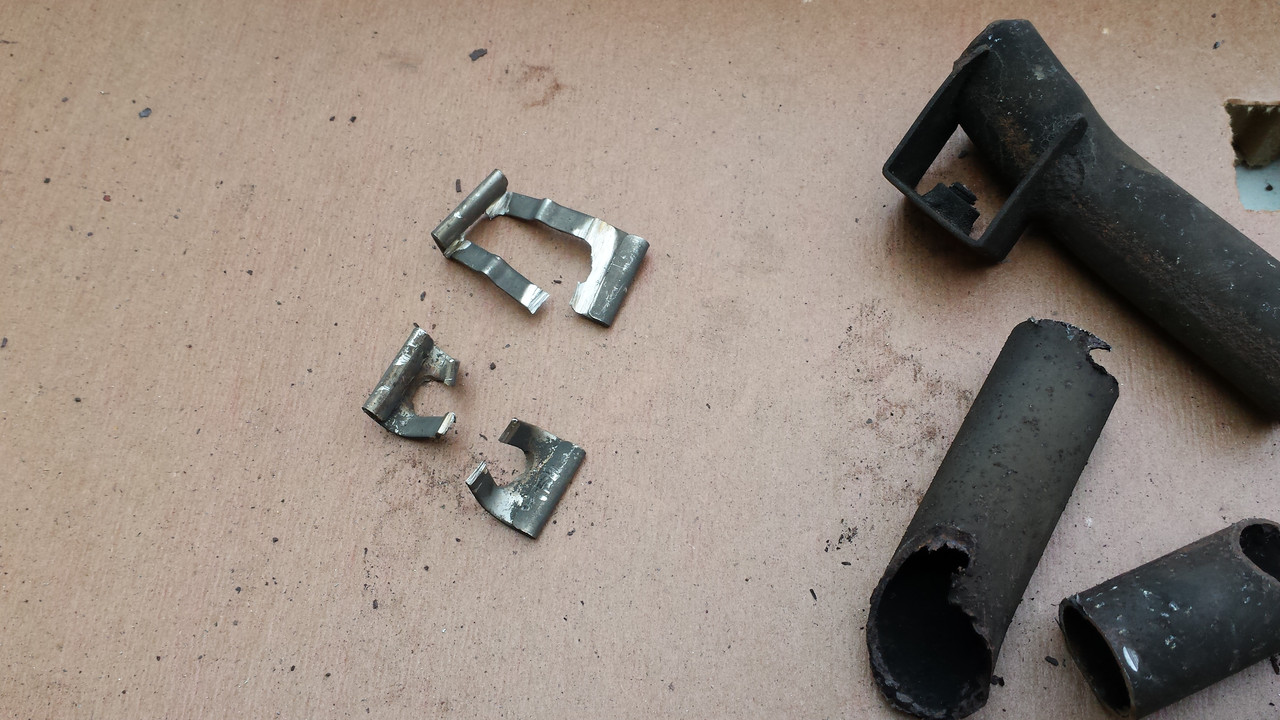 Then a wire brush onto an electric drill, and all over the mufflers, cleaning them up of the grime and rust that was there. In the end, I liked them. All they need is a little cleaner, and a little coat of high temp paint. It might make the stacks a little tighter on the muffler, but I hope I wont have the same rust build up, incase of later removal. 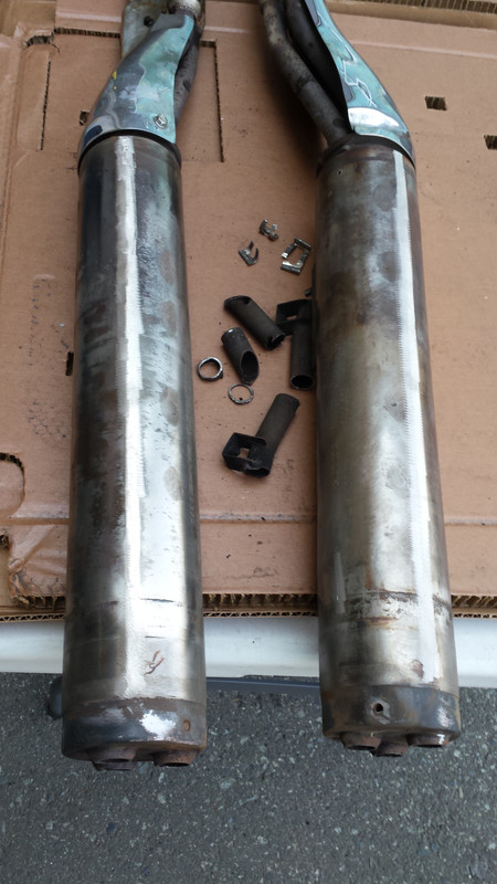 I didn't have the 1/2" NPT tap and copper couplers on me, so I pulled a stack out of the box to see how easily it might slide onto the muffler, and compare it's length on the Valkyrie, and what do I see? A straight end pipe, on both ends. WTF! I had ordered up a pair of 45' slash cuts, and paid for them, and waited a month for delivery. Now what was I going to do? I know I need to call up the store first (closed weekends). But if they can't/wont exchange them. Do I go with square cut? Looks nice with those billet end pieces. But I've been liking the idea of the slash cut out to the side, with exposed piggies coming out. Oh well, wait till Monday. So for now, I need to wait. Next is to tap the exhaust ports threaded to accept the couplers. That is going to be fun, to tap it straight, free hand. I'll see if there might be a way to get the tap into a socket, and at least use a drill. I think this would be easier to keep it straight. But I hope I can force the inserted 3/4" copper pipe into the direction I want, to have them align out the end of the stack. |
|
|
|
« Last Edit: April 30, 2018, 08:22:54 PM by gordonv »
|
 Logged
|
1999 Black with custom paint IS 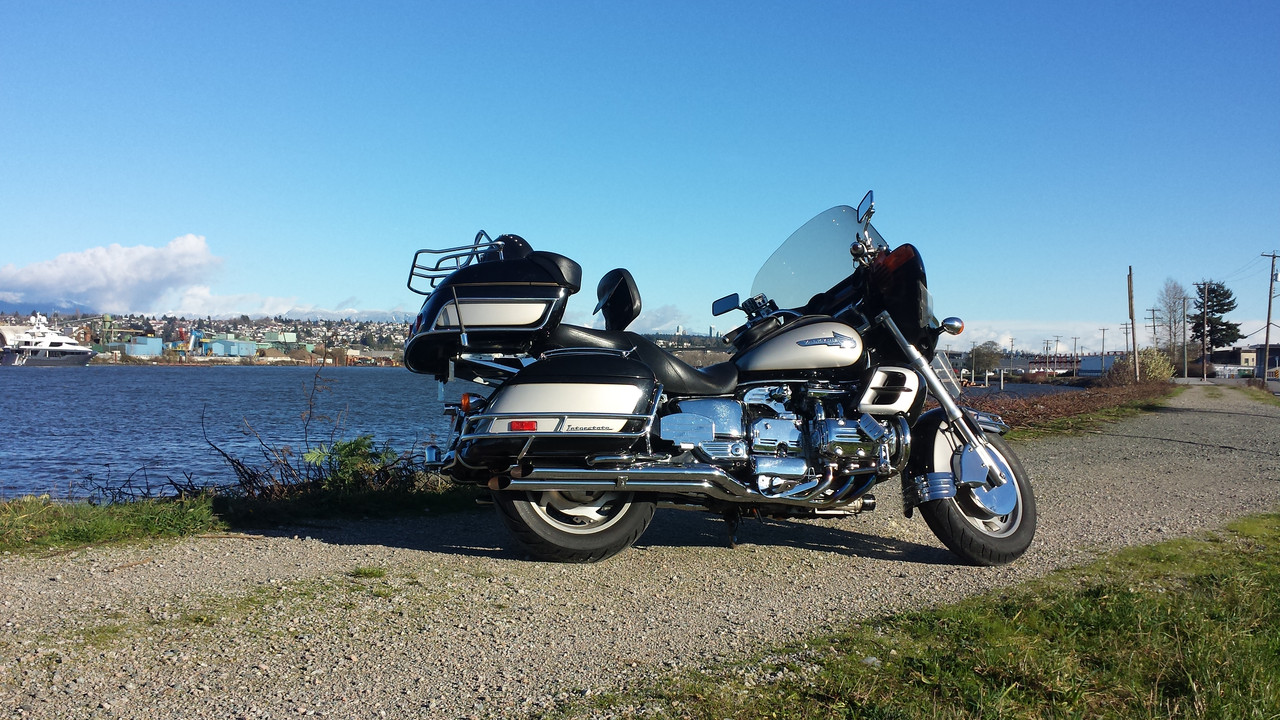  |
|
|
gordonv
Member
    
Posts: 5766
VRCC # 31419
Richmond BC
|
 |
« Reply #1 on: August 14, 2017, 06:32:29 PM » |
|
I bought the paint today, some high temp exhaust. Touched up the muffler, and also along the pipes that weren't chromed. 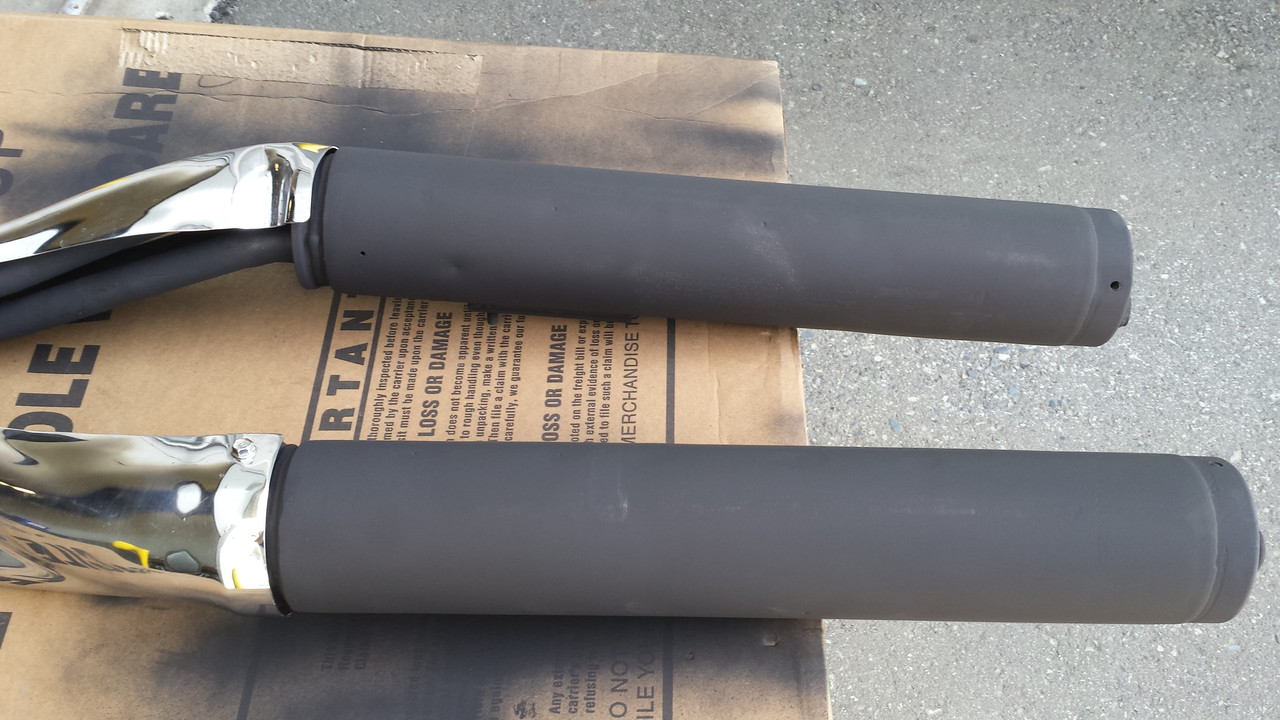 Called up the exhaust supplier. They said bring it in. I found the receipt, and it does say mitered, so if they ordered or got the wrong item, they'll make it good. Of cource, I'll need to wait for shipping again. |
|
|
|
« Last Edit: April 30, 2018, 08:23:38 PM by gordonv »
|
 Logged
|
1999 Black with custom paint IS   |
|
|
gordonv
Member
    
Posts: 5766
VRCC # 31419
Richmond BC
|
 |
« Reply #2 on: August 15, 2017, 05:36:11 PM » |
|
Another day, and another bit of work on the exhaust. Today, brought the tap and couplers to work. Found my 12 point sockets, and 5/8" fit the tap nicely. Got out the impact wrench, and started to tap the exhaust ports. A little fun trying to square it up, on slow speed helped, and on a few of them, it just didn't want to bit and start to thread in. But in the end, they all got done. Screw in the brass couplers, to check out the thread and how square of a job I did. Some where perfect, others not bad, but one was really bad, off to the side of the muffler. I REALLY hope that I can force the 3/4" copper pipe into it, and bend it just enough to align properly out the end of the truck stack. But that will need to wait. 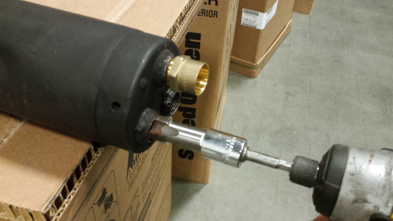 I returned the truck stacks to the purchaser. They took them back, and will do their best to get me the right ones asap. So far, I've been very pleased with their service and attitude. They are waiting till I'm done, so they can see what I've been doing. |
|
|
|
« Last Edit: April 30, 2018, 08:24:50 PM by gordonv »
|
 Logged
|
1999 Black with custom paint IS   |
|
|
gordonv
Member
    
Posts: 5766
VRCC # 31419
Richmond BC
|
 |
« Reply #3 on: October 19, 2017, 07:29:13 PM » |
|
It's been a while since I've worked on this. The replacement stacks came in, and they were the right ones. I researched prices on 3/4" copper pipe, and found a 10' length at Lowe's for about half of other places, and also picked up a pipe cutter. I cut up 6 pieces of equal length, 14 1/2", placed them in the couplers, and they look nice. One coupler is not aligned, so I hope I can heat and bend it a little. I think I'll cut a notch in that pipe. 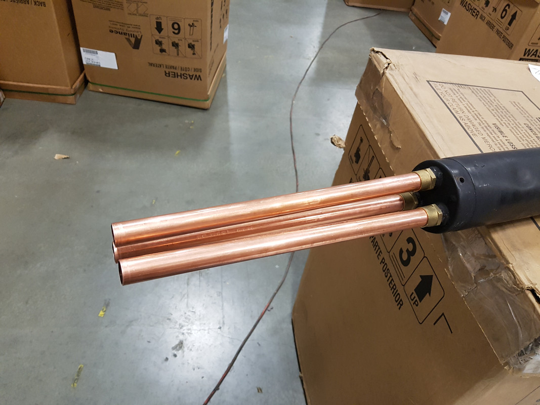 Then I put into practice the method suggested in aligning the stacks. An equal height item, a level, to get the 2 stacks matching. 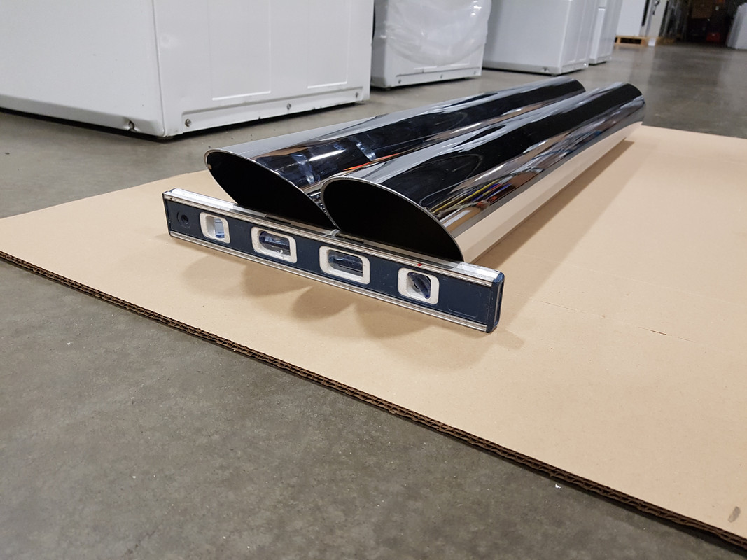 Then I marked 9" from the square front of the pipes, ran 2 strips of 2" masking tape down the 12 o'clock position, then how to run a line down that point? A piece of pipe! Roll it along the top, and you can see where it pressed the masking tape down, creating a line. 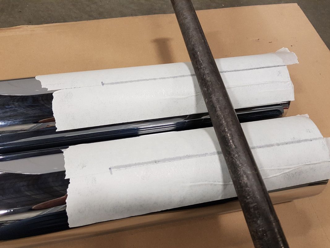 Then peeled off another length of 2" masking tape, folded it down the middle and marked a few points in the center. Then laid that down with the marks on the alignment marks I made with the pipe on the tape. Then again marked it to the 9" mark. 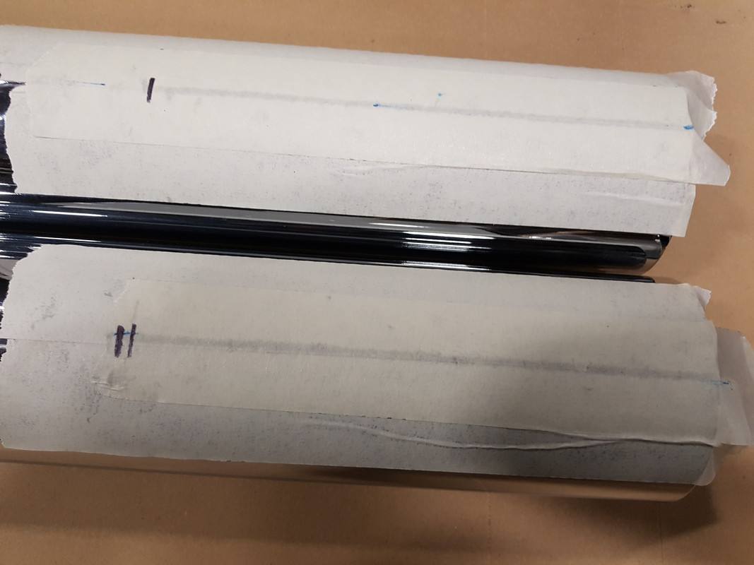 Then out comes the cutter. A Dremel with a metal cutting wheel. 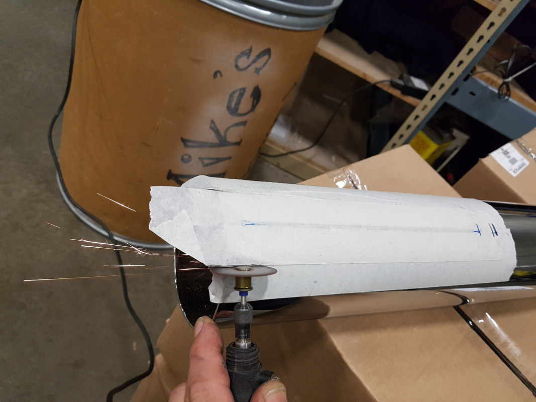 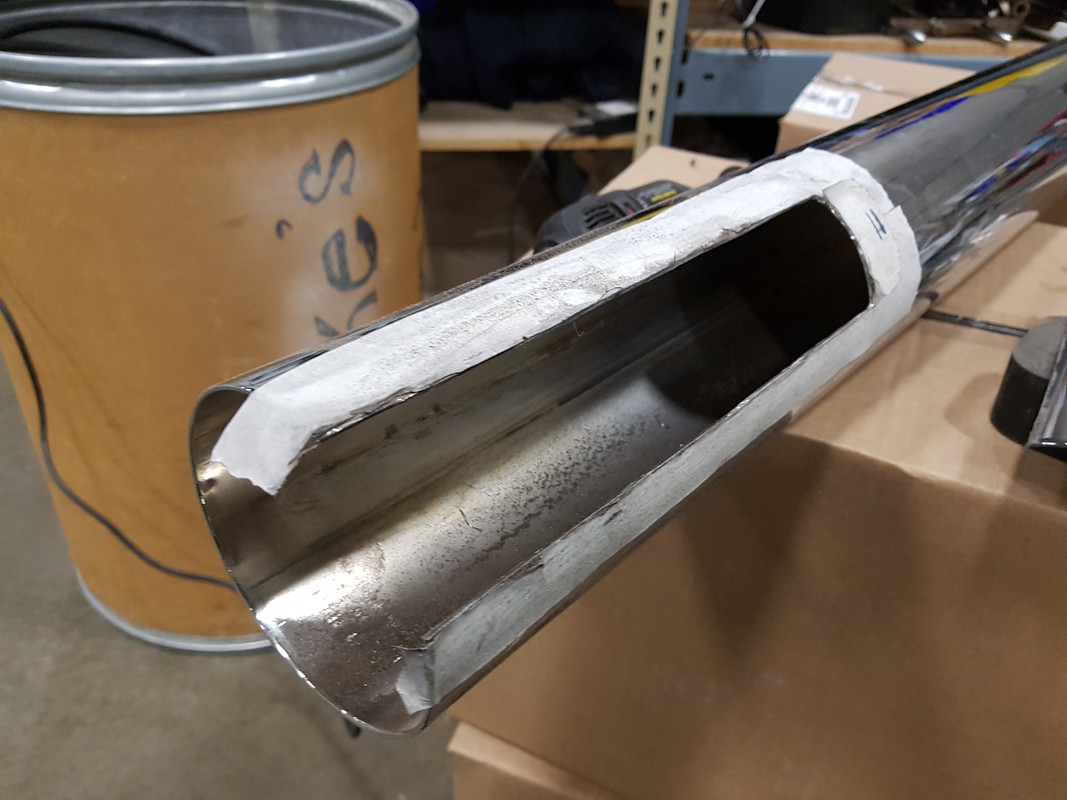 Cleaned it up so nothing to cut you when you handle it. Now I'm looking for a support for the copper pipes. Want to place another 2" length of pipe inside of the triangle of the 3 exhaust pipes, and soldier it in place. I found a length of plastic that seems to be the right OD, now just need to find something in metal. Now for those who have soldiered their copper pipes in, what type of soldier did you use? Just regular plumbing tin/silver soldier, brazing rod? |
|
|
|
« Last Edit: April 30, 2018, 08:27:43 PM by gordonv »
|
 Logged
|
1999 Black with custom paint IS   |
|
|
|
Cracker Jack
|
 |
« Reply #4 on: October 19, 2017, 10:21:50 PM » |
|
It's been a while since I've worked on this. The replacement stacks came in, and they where the right ones. I researched prices on 3/4" copper pipe, and found a 10' length at Lowe's for about half of other places, and also picked up a pipe cutter. I cut up 6 pieces of equal length, 14 1/2", placed them in the couplers, and they look nice. One coupler is not aligned, so I hope I can heat and bend it a little. I think I'll cut a notch in that pipe.  Then I put into practice the method suggested in aligning the stacks. An equal height item, a level, to get the 2 stacks matching.  Then I marked 9" from the square front of the pipes, ran 2 strips of 2" masking tape down the 12 o'clock position, then how to run a line down that point? A piece of pipe! Roll it along the top, and you can see where it pressed the masking tape down, creating a line.  Then peeled off another length of 2" masking tape, folded it down the middle and marked a few points in the center. Then laid that down with the marks on the alignment marks I made with the pipe on the tape. Then again marked it to the 9" mark.  Then out comes the cutter. A Dremel with a metal cutting wheel.   Cleaned it up so nothing to cut you when you handle it. Now I'm looking for a support for the copper pipes. Want to place another 2" length of pipe inside of the triangle of the 3 exhaust pipes, and soldier it in place. I found a length of plastic that seems to be the right OD, now just need to find something in metal. Now for those who have soldiered their copper pipes in, what type of soldier did you use? Just regular plumbing tin/silver soldier, brazing rod? Maybe a typo, but...and they WERE the right ones. Not,..."and they where the right ones." |
|
|
|
|
 Logged
|
|
|
|
Houdini
Member
    
Posts: 1975
VRCC #28458 - VRCCDS#144
Allen, TX
|
 |
« Reply #5 on: October 20, 2017, 06:37:13 AM » |
|
Now for those who have soldiered their copper pipes in, what type of soldier did you use? Just regular plumbing tin/silver soldier, brazing rod? I tried regular tin plumbing solder and lost a pipe on my first ride. I tried silver solder and when I arrived home one pipe was lying in the bottom of my truck stack and three more were moving out of the coupling but had not completely fallen out. My Acetylene tank was empty so I couldn't braze them so I ended up drilling a small hole in each coupling and used a small screw to hold them in place, they've been that way for over two years now. PS. Am I the only one that gets annoyed when someone quotes a long post with lots of pics just to call out a typo? |
|
|
|
|
 Logged
|
"A Camera And A Bike....What More Do I Need?  |
|
|
gordonv
Member
    
Posts: 5766
VRCC # 31419
Richmond BC
|
 |
« Reply #6 on: October 20, 2017, 10:02:42 PM » |
|
Now for those who have soldiered their copper pipes in, what type of soldier did you use? Just regular plumbing tin/silver soldier, brazing rod? I tried regular tin plumbing solder and lost a pipe on my first ride. I tried silver solder and when I arrived home one pipe was lying in the bottom of my truck stack and three more were moving out of the coupling but had not completely fallen out. My Acetylene tank was empty so I couldn't braze them so I ended up drilling a small hole in each coupling and used a small screw to hold them in place, they've been that way for over two years now. PS. Am I the only one that gets annoyed when someone quotes a long post with lots of pics just to call out a typo? So as I suspected, any low melting point soldier, tin, silver, won't work. You need to braze them in, or just the heat of riding will melt the soldier. I like the idea of a screw. Might do that just to hold the pipes in proper alignment, before brazing them in. Now to get the pipes aligned. I think a piece of angle iron, running the length of the muffler to the end of the copper pipes. |
|
|
|
|
 Logged
|
1999 Black with custom paint IS   |
|
|
|
|
gordonv
Member
    
Posts: 5766
VRCC # 31419
Richmond BC
|
 |
« Reply #8 on: March 09, 2019, 07:04:48 PM » |
|
It's be along time, 1.5 years, am I a procrastinator or am I not?  I tried a few different things to try to get those copper pipes aligned, without success. So I unscrewed the couplers, and heated up the 4" pipe, and then BANGED then onto the front mufflers as fast as I could, by driving it into a wooden skid on the ground. Bent the tip a little, but that should be fixable.  The alignment for the hanger and the angle I wanted the slash cut at, was correct. The hanger studs are horizontal. As for the missing pipes to get the sound out of the resonator chamber? I had bought a set of those 4" marine slip in silencers. https://www.hardin-marine.com/p-12622-4-slip-in-silencer.aspxThey fit the pipe nicely. But since I hadn't installed my truck stacked exhaust onto my bike, I "lent" them to msb for his exhaust. He tried them out and loved the new sound he got. A little quieter on those longer drives for him and Lisa. Now he just needs to buy me another pair, to replace them. Now they are awaiting the end of my winter projects. It'll most likely be the last thing I install, after my replacement rear black powder coated rim and Austin Taxi Tire. |
|
|
|
« Last Edit: March 09, 2019, 08:12:20 PM by gordonv »
|
 Logged
|
1999 Black with custom paint IS   |
|
|
gordonv
Member
    
Posts: 5766
VRCC # 31419
Richmond BC
|
 |
« Reply #9 on: March 09, 2019, 07:40:10 PM » |
|
I've been spending the last year getting everything together for when I strip the engine down. First bought the cheapo parts for a desmog, and in the end, just bought Redeyes kit. Below is me tearing everything off, preparing the bike for the projects I have coming up. 1st the tank.  Petcock didn't seem to leak, but the tank was almost empty, so I left it for later. I didn't want to spend an hour trying to figure it out and fix it now. I'll do this later, when I decide on vacuum shut off, rebuild (bought a kit), pingle (from a Shadow) and or an electric fuel pump (also off a Shadow). What is that under the bib? A decal that has been pealed away, from the heat and rubbing from the bib. It's a mess under there. Now how will my new 2 pouch Iron Horse bib cover it up? I'll have to wait and see. 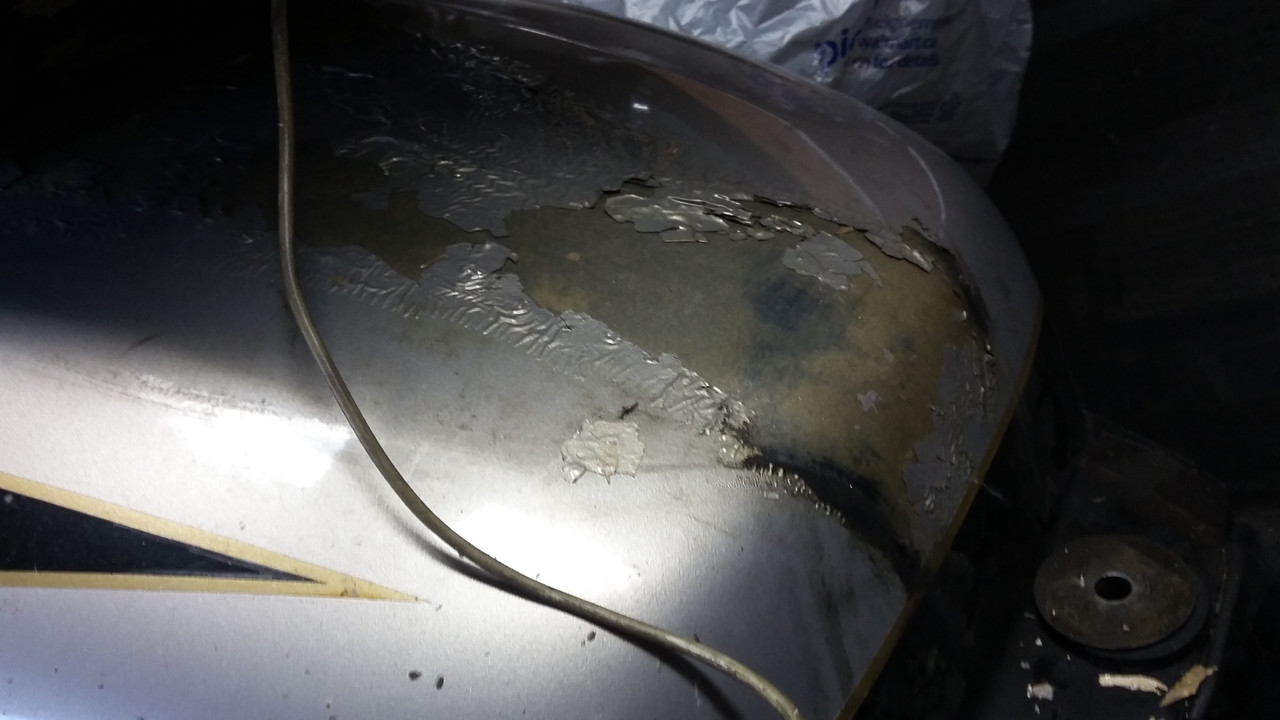 What's this? The PO had an Apple power source in the bib pouch, plugged into a USB socket, which was wired to the battery. That's what this mess was under all this electrical tape.  Then there is the reason for new o-rings for the intake runners. leakage/staining around the seal.  Now what is the brownish tube behind the intake? Oh, that's what the light is coming from I see at night. Some kind of accent lighting. Just another thing to remove, and have another reason to wire in that fuse block I picked up earlier, to have an external power block off of the battery, since everything was plugged into it. For those doing a desmog, one of these impact driver.  I had bought it when I was stripping down my wrecked IS in 2011, the cover screws on the brake/clutch reservoir would not loosen. There was mention that the 2 screws holding the center valve were hard to loosen, so I tapped each, and off they came. I got the air box out. Removed the clutch cable, and paused on the throttles. Had nothing on hand to label the 2 cables that were going to be disconnected, and stopped there. I have at home some key tags, string with cardboard tags, so I can write Left/Right on them. I also started to remove some of the vacuum lines. Since there is how-tos posted already, I wont dwell on things that I might be repeating. I did some more research, looking for posts on how to remove the carbs from the side. Found what I think I'm looking for and needed. After re-reading it, cleaning it up for clarity, organizing it so it is understandable, I'll use this method to remove my carbs the rest of the way. After proving it right, and cleaning it up further, I'll post it here for others. |
|
|
|
« Last Edit: March 09, 2019, 08:37:26 PM by gordonv »
|
 Logged
|
1999 Black with custom paint IS   |
|
|
LB
Member
    
Posts: 84
2003
Upstate South Carolina
|
 |
« Reply #10 on: March 10, 2019, 05:35:42 AM » |
|
Now for those who have soldiered their copper pipes in, what type of soldier did you use? Just regular plumbing tin/silver soldier, brazing rod? I tried regular tin plumbing solder and lost a pipe on my first ride. I tried silver solder and when I arrived home one pipe was lying in the bottom of my truck stack and three more were moving out of the coupling but had not completely fallen out. My Acetylene tank was empty so I couldn't braze them so I ended up drilling a small hole in each coupling and used a small screw to hold them in place, they've been that way for over two years now. PS. Am I the only one that gets annoyed when someone quotes a long post with lots of pics just to call out a typo? No you are not … people that point out typos have way too much time on their hands and really need to get a hobby. |
|
|
|
|
 Logged
|
|
|
|
|
Beardo
|
 |
« Reply #11 on: March 10, 2019, 07:25:36 AM » |
|
Good luck man. Looks like fun.
Noting worse than trying to figure out someone else’s hatchet job “improvements”.
|
|
|
|
|
 Logged
|
|
|
|
gordonv
Member
    
Posts: 5766
VRCC # 31419
Richmond BC
|
 |
« Reply #12 on: March 10, 2019, 08:10:07 AM » |
|
Good luck man. Looks like fun.
Noting worse than trying to figure out someone else’s hatchet job “improvements”.
Hey, I resemble that remark.  But ya, sometimes hard to figure out what was done and why. In this case, it's easier, I'm digging deep, so most things are coming off, and then going back in. I never did post what I'm doing, and my list is at the garage. But I have about a 3/4 page of things to do. All I'm trying to have done in time for maintenance day in Apr, but this might not happen, so I'll just take the convertible there instead. Some things are simple, intake o-rings, but others require more work. But all are easier to do while the air box/tank/carbs are out of the way. I think a picture of all the parts will give a better idea too. Oh, 1 there thing I found. Mold!! Mold under the tank, on the lines, under the air box, all over the places you can't see on top of the engine. There is nothing there organic, what could it be coming from? The bike is stored dry for more time that it is ever seeing water. The water wouldn't stay long, as the heat of the engine should dry it off. Maybe protein matter? Bugs and the like, splat!! I know I was going to spend time cleaning in there when I had the air box off, but this was strange. |
|
|
|
« Last Edit: May 18, 2019, 07:24:27 PM by gordonv »
|
 Logged
|
1999 Black with custom paint IS   |
|
|
gordonv
Member
    
Posts: 5766
VRCC # 31419
Richmond BC
|
 |
« Reply #13 on: March 17, 2019, 11:49:03 AM » |
|
What I'm trying to do, before ridding season starts here.
Things to do, in order;
4" truck stacks & piggies exhaust (done, need to swap out and get the silencers)
things to do when tank is off the bike:
explore the petcock, not working on hwy shut off
desmog at the same time
intake o-rings
electric fuel pump
Audiovox CC
wire antenna
move horn back to engine - add relay and replace with high/low 135 DB pair of horns
BonS headlight power lead
need to replace the IS front turn signals
LED instrument light bulbs
USB not working, fix and add an on/off switch to it, or accessory power
alternator clean/inspect, brushes
paint wrinkled chrome alt cover
install CB
fix leak in trailer
Install battery into trailer
Add power line to trailer to charge battery
Add LED lighting and switch to inside of trailer
Re-wire trailer. Remove connectors
swap trailer hitch & connector on mc
brake light add-on rear fender
brake light on trunk, LED from Astro van
rear ATT wheel swap
Goldwing valve covers, black
neutral switch swap to GW OD switch
add LED gear indicator
GL1800 spoiler, fits trunk lid
drivers back rest, swap out the Ultimate for the OEM
I've grouped them in order of needing to be done. All those items when the air box is off, then next important, and so on.
|
|
|
|
« Last Edit: June 28, 2020, 09:17:03 AM by gordonv »
|
 Logged
|
1999 Black with custom paint IS   |
|
|
gordonv
Member
    
Posts: 5766
VRCC # 31419
Richmond BC
|
 |
« Reply #14 on: March 17, 2019, 11:50:49 AM » |
|
Here is that mold I mentioned, under the tank, air box, and on those hoses.  I did not take a picture yet of the air tubes to the cylinder heads, and having only removed the one side, I found the No 4 air tube was blocked with ash (?), no air going through it. All that soot from the exhaust, has been filling up my 100K miles air tubes. No back firing. No other known signs of issues. |
|
|
|
« Last Edit: April 07, 2019, 11:42:17 AM by gordonv »
|
 Logged
|
1999 Black with custom paint IS   |
|
|
gordonv
Member
    
Posts: 5766
VRCC # 31419
Richmond BC
|
 |
« Reply #15 on: April 07, 2019, 12:16:46 PM » |
|
Are the air tubes needed? Not this one, it's 100% blocked. The other one was about 50% blocked.  Then those o-rings on our intake runners. Mine must have gone cheap, because someone used washers instead. (they're not washers, just flat hardened rubber) 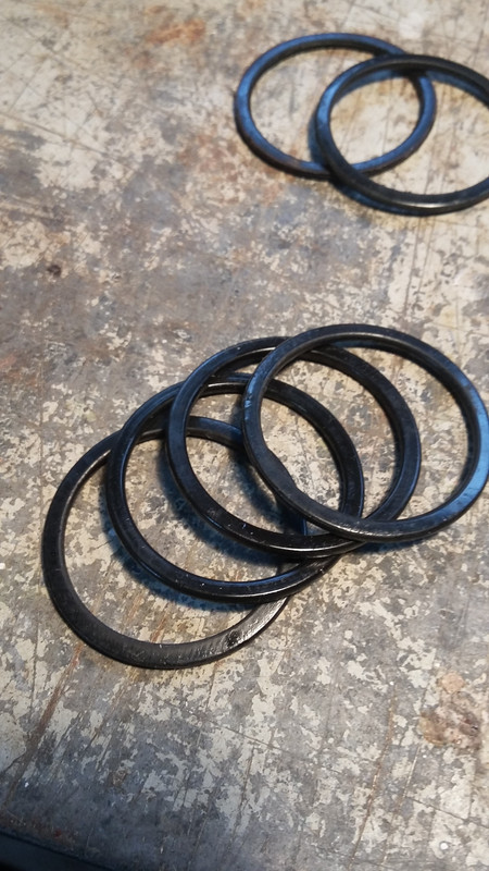 The leakage from the intakes was like tar. I spent 1/2 hr trying to clean one small section and still needed to do more. I didn't want to scratch the engine. I completed the desmog. Got the carbs and intakes back in place. Hooked up the chock and throttle cables, but had no clue how to adjust them. Chock, not needed. Throttle, looked it up. Seems simple, there is 2-6 mm of play in the handle, seems easy enough too. Spent some time getting the rear engine hangers back on. Right side fine. Replaced the chrome ignition cover for a black one off a Shadow. The left side, I had removed the chrome hanger covers and the coil pack was never connected properly. After researching, seems the wrong bolts where used, and the spacers missing, so the bracket has been totally bent out of shape. It should be flat, but it's warped in 3 places. I need to remove it, and hammer/bend it flat again. I removed the alternator, came out in about 5 min. Took it apart, inspected the brushes, cleaned it out. Could see the holes in the brushes to pull the brushes in and lock them in. Figure that leaves me with another 25K miles on the alternator. Found the missing spacers for the rear coil pack. Had fallen between the alt and the engine block. Spent about 15 min getting the alternator back into the engine. addition of link to my alternator replacement thread http://www.valkyrieforum.com/bbs/index.php/topic,107156.0.html |
|
|
|
« Last Edit: November 08, 2020, 03:33:40 PM by gordonv »
|
 Logged
|
1999 Black with custom paint IS   |
|
|
gordonv
Member
    
Posts: 5766
VRCC # 31419
Richmond BC
|
 |
« Reply #16 on: April 07, 2019, 12:36:20 PM » |
|
Onto the fairing. Removed the left side cover, disconnected the speaker wire, looked into disconnecting the heated grip switch, but WTF it's hard wired in. Found some loose bare wires, and electrical tape came off the wiring.
Another project. Fixing the PO work. I had bought a set of connectors off ebay. A bunch off 2-9 pin connectors. Looks like I'll be using some of those after I figure out how many wires are needed to connect together. Make the inner fairing cover removable, and the wiring dis-connectable.
Stopped for the day, but need to remove the other side and then the fairing.
I decided not to install the electric fuel pump, yet, but to leave it for another date. Not knowing how to wire it in properly, where to draw the power signal from, or how much psi the pump will deliver.
Now to read over the how-to on installing the CC again.
|
|
|
|
« Last Edit: April 07, 2019, 12:45:05 PM by gordonv »
|
 Logged
|
1999 Black with custom paint IS   |
|
|
|
3W-lonerider
|
 |
« Reply #17 on: April 07, 2019, 02:01:28 PM » |
|
you might want to reconsider the fuel pump idea if you don't have a belly tank.
i tried installing a fuel pump and electric shutoff on a plate that was held on by the kickstand bolts.
i got a 2.5 to 3 psi pump.
had to remove it because it was pushing past the floats and flooding the engine while running.
don't know if the load from the fuel tank pushing threw the pump while the pump was in operation was a result or not. but just letting you know my experience.
|
|
|
|
|
 Logged
|
|
|
|
gordonv
Member
    
Posts: 5766
VRCC # 31419
Richmond BC
|
 |
« Reply #18 on: April 07, 2019, 08:24:16 PM » |
|
you might want to reconsider the fuel pump idea if you don't have a belly tank.
i tried installing a fuel pump and electric shutoff on a plate that was held on by the kickstand bolts.
i got a 2.5 to 3 psi pump.
had to remove it because it was pushing past the floats and flooding the engine while running.
don't know if the load from the fuel tank pushing threw the pump while the pump was in operation was a result or not. but just letting you know my experience.
One reason I'm holding off on the pump. I've gotten one off a Shadow ACE T. I want to get a pressure gauge and see what psi it pumps out. The ACE T is 1100 cc and 2 carbs. I was thinking it could be used in place of a Dan Marc fuel shut off, but need to confirm no fuel flow when not pumping, and allow me to add a normal inline fuel filter. I know there is a flow rate test for the pump. Would need to see what kind of rate there is for the Valk. From the manual, 800 cm3 (27.1 US oz, 28.2 imp oz) / minute. I'm thinking powering the pump from one coil, which would be 1 pulse every 360'. I need to do more pictures too. Kind of dry without them, and I'm not a great writer. |
|
|
|
« Last Edit: April 07, 2019, 08:45:21 PM by gordonv »
|
 Logged
|
1999 Black with custom paint IS   |
|
|
|
Bagger John - #3785
|
 |
« Reply #19 on: April 09, 2019, 05:47:04 AM » |
|
...Replaced the chrome ignition cover for a black one off a Shadow...
Which year and model did the cover come from - any idea? |
|
|
|
|
 Logged
|
|
|
|
nogrey
Member
    
Posts: 939
Live every day as if it were your last
Nampa, Idaho

|
 |
« Reply #20 on: April 09, 2019, 09:54:04 AM » |
|
Enjoying the write-up and photos. Great work on the pipes, they look very nice. I like the way you re-threaded the piggies. I don’t weld (always wished I’d taken classes) so I’d have used screws and permatex high-temp. Just went through a “new” interstate. Finished it last month. I did the supervalk thing. I really like it. I put a battery mounted 4 fuse marine block on the battery. It fit nicely but I did have to modify the top cover. I also put a 6 fuse block in the fairing. I ran power to it through a 12 ga wire set that is operated by a relay from the ignition. Also marine grade and fairly well protected behind the fairing there. I saw in your list of items a BonS power bypass for the headlights. Let me know if you can get one as I thought he had stopped selling them. I made my own using his same method, just doesn’t look as pretty. Looking forward to seeing your finished machine.
|
|
|
|
|
 Logged
|
|
|
|
gordonv
Member
    
Posts: 5766
VRCC # 31419
Richmond BC
|
 |
« Reply #21 on: April 09, 2019, 05:19:51 PM » |
|
...Replaced the chrome ignition cover for a black one off a Shadow...
Which year and model did the cover come from - any idea? I thought it was from a VT1100T. But you can't tell on the fiche. Searched ebay. The VT1100T showed a chrome ignition cover. There was a 750 ACE which had the black plastic one. I saw in your list of items a BonS power bypass for the headlights. Let me know if you can get one as I thought he had stopped selling them.
msb and I bought up 2 when BonS advertised he was going to stop making them. Even thou we both have the IS, which already uses relays to bypass the power through the starter switch. As for the exhaust, I gave it up. I couldn't get the tubs aligned. So I forced on the stacks and have bought a set of the slip in silencers. The exhaust will be the last thing installed on the bike, so pictures while be a while in coming. |
|
|
|
|
 Logged
|
1999 Black with custom paint IS   |
|
|
|
Bagger John - #3785
|
 |
« Reply #22 on: April 10, 2019, 06:52:17 AM » |
|
...I thought it was from a VT1100T. But you can't tell on the fiche. Searched ebay. The VT1100T showed a chrome ignition cover. There was a 750 ACE which had the black plastic one...
After I posted the question I went scouring the 'Bay and got what looks like a black plastic one from a Shadow. Fingers crossed. As a side note, I really ought to buy stock in whomever makes black powdercoat.  |
|
|
|
|
 Logged
|
|
|
|
gordonv
Member
    
Posts: 5766
VRCC # 31419
Richmond BC
|
 |
« Reply #23 on: April 13, 2019, 08:37:10 PM » |
|
Another Saturday, and another day working on the bike. It was productive, but a lot of failures too. Here's a pic of the black ignition cover. Seems what looks good on my cell, doesn't look very nice on the pc at full size. 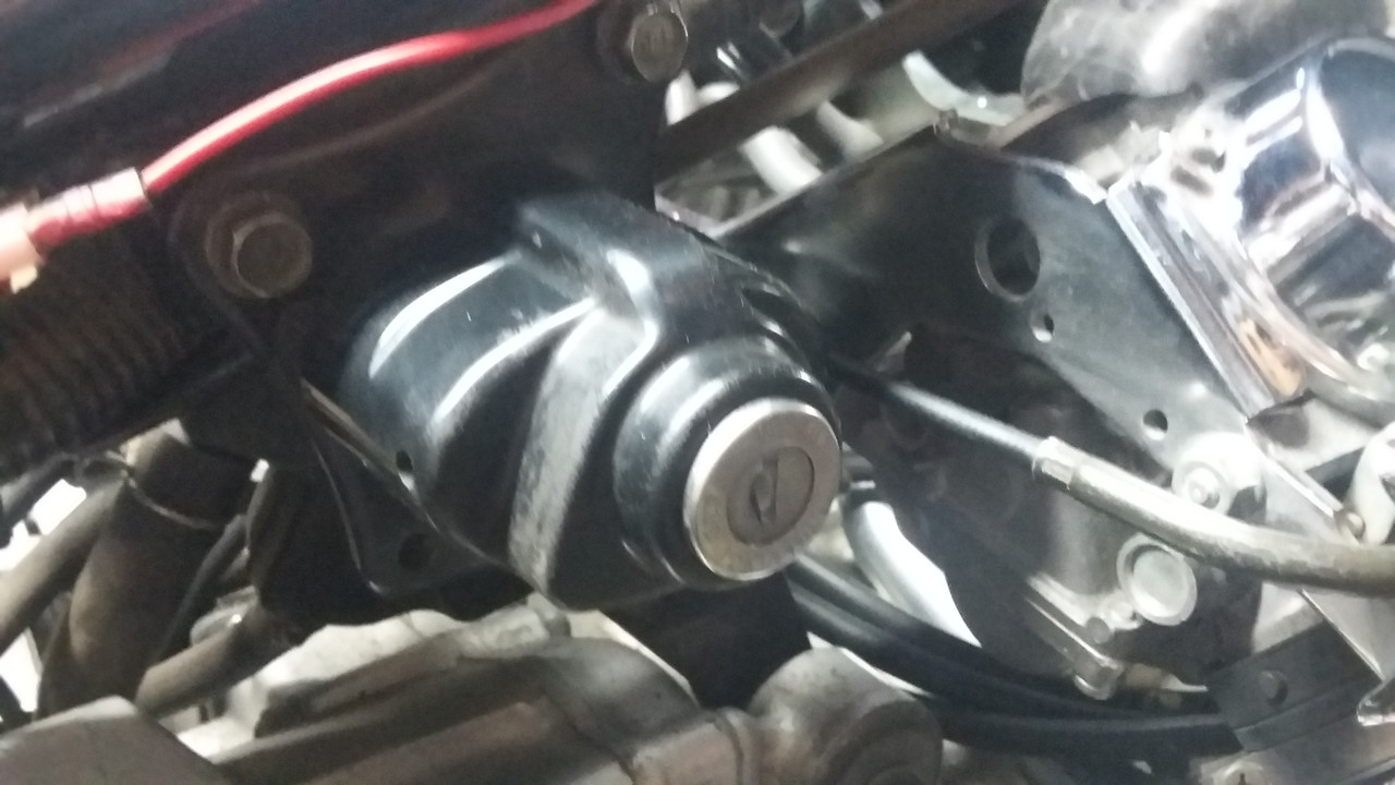 Then the first job was trying to fix the coil mount bracket, so I can have the proper surface for placing it on the rear hanger and get the fuel select lever mounted properly. This is the reason this wasn't connected to my petcock in the first place. 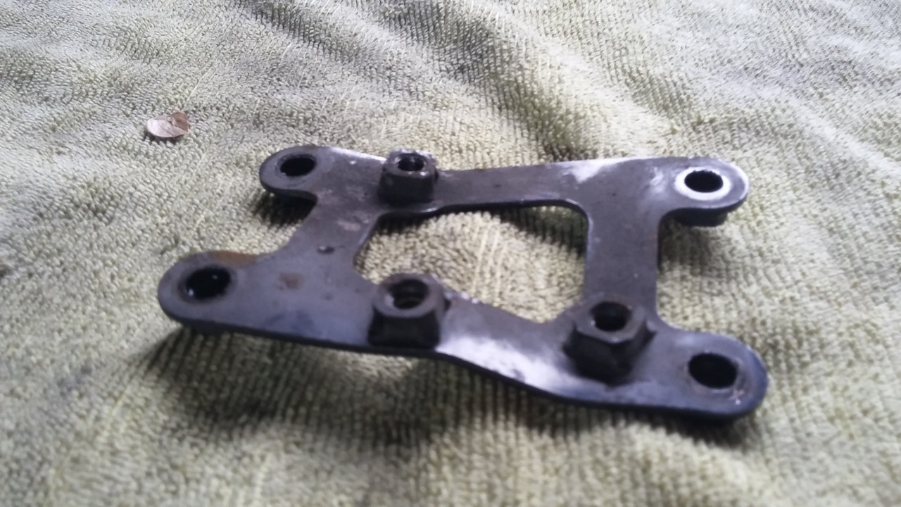 Good thing I've a small bench vise and some channel locks, I was able to get it almost flat again. Nuts welded on each side, so I placed a larger nut on the other side and placed the plate in the vise, which gave me good points to bend the metal on. It was really soft metal, so you need to take care when playing with those 3 bolts which mount it onto the hanger, or the petcock selector. I got the front fairing off, pic doesn't look as nice as I thought it did. There's from the left, the headlight modulator, horn, black box on the upper triple tree, can't see the electronic deer horn on the lower triple tree, a bunch of wires with unknown uses.  This block on the fork, the switch for my heated grips, and the wires match up, so I figure it's some kind of heat sink or fuse? 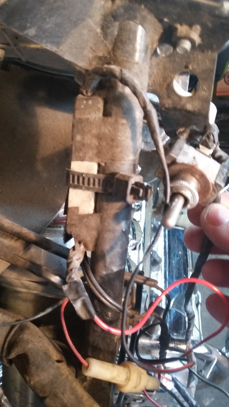 So, first step was to clean some things up. Take the horn off, follow the leads back to figure out where they came from. Followed them back to the frame neck, right side, off came the neck cover, unwrap the electrical tape, and I find what looks like the OEM plugs for the horn. These would have come from the lower right bolt of the engine guard. 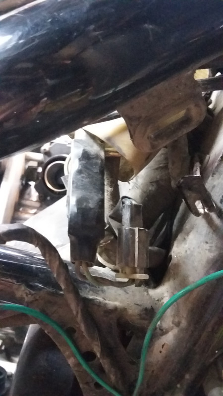 But what else do I see? Could that be the CB noise suppressor? There used to be a CB on the bike, that was removed by a PO. Back to the horn. Here is a new set I bought, was rated at 135db. OK, mount one on the right engine guard bolt, the other on the left. Point then inwards, since the water hose is in the way. Seems to be enough room for the front wheel fender.  Gampro horns, 135db https://www.amazon.com/gp/product/B0799CQKSP/ref=ppx_yo_dt_b_asin_title_o04_s00?ie=UTF8&psc=1Cut the wire, add connectors, and bring it up to the frame neck. Mount them onto the relay that came with the horns. 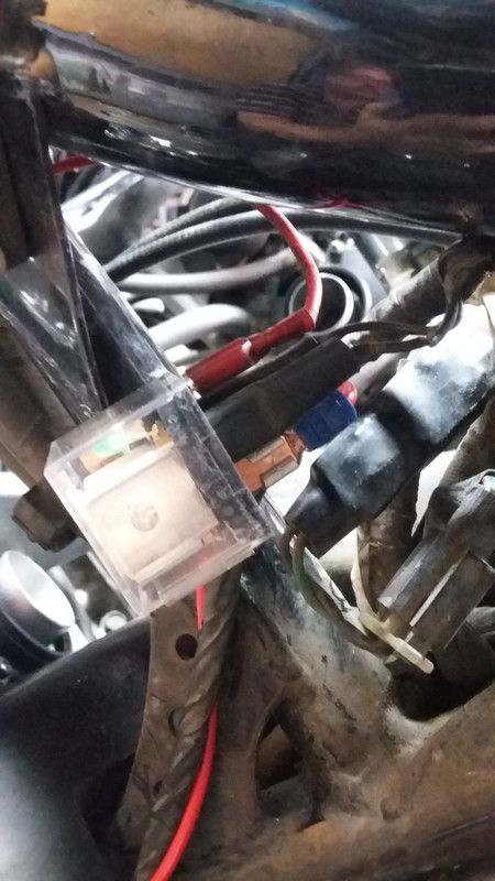 String the power from the battery/relay/horns. Try them out. Ohhhh, it was the same beep of an OEM horn. I'm looking for loud. Something to be heard when I hit the button. Oh well, lets try the set of high/low horns off of a GL1800, I know they are better than a GL1500. Rated at 108db. OK, sounded better as a set (I had only mounted one in the fairing to replace the OEM horn that was in there and not working), more like a car than a MC, but not as loud as I would like. But I can work with this for now. Later I'll replace the red wire for some black to hide it. 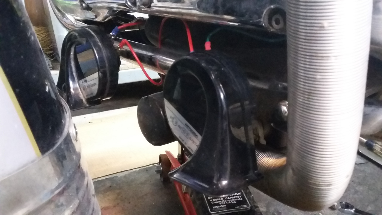 Next was to replace those dash lighting lamps with the Superbrite LED ones.  Pull out one from the dash, and what do I see, a small lamp about 1/6 the size of the ones I bought. It was also black, most likely burnt out, but not the match to what I bought. I must have miss-read the ones used and bought for the std/Tourer model instead, and I bought 8 LEDs (2 sets of 4) so I could do someone else's IS too, and now it looks like I have enough for 4 sets of 2, for a std/Tourer. (seems I should have ordered these. 74 LED Bulb - 3 SMD LED - Miniature Wedge Base - Cool White. Ordered now) OK, onto the next one. The Smartswitch for an IS.  Unpack, lay it out, the harness from the battery to the front routed properly. Plug it into the headlight sockets, figure out which set of plugs into which connector. Plug in the sockets, get some zap straps onto the sockets to hold them in place and not fall apart. This happened to me on the ride out to Billings InZane, head lights went out. Found that the sockets unplugged. Applied a zap strap to hold it closed. This was also suggested in the instructions from BonS.  Placed a set of the OEM bulbs in, turned on the ignition, and Nothing! What now? Ah, mount the harness to the battery, I didn't want to play with live wires when figuring it out. Connect to the battery and try again. Nothing! OK, remove one bulb and place it in the OEM wire harness, try again, and the OEM works, so why not the Smartswitch? Well, I have a head light modulator, so remove this from the circuit, and try again. All works with the OEM harness. Add the Smartswitch to one side, and the OEM on the other. It works, so I figure that there must not be enough of a signal from the modulator to work with the Smartswitch. See how much better or not the direct power from the battery to bulb might be. Turn it on, and I can't see enough of a difference to want to remove my modulator from the circuit. So off comes the whole Smartswitch, and wire the head light modulator back in properly. Now to figure out some of those wires, and what that black box is. How's it mounted? Pull on it, and it comes off, double sided tape.  And there's writing on it. AMPERITE 12D1BUZ . It's wired into the front turn signals, 2 black and one red wire. The black to the turn signals, and the red to what looks like ground. Oh ya, I have a turn signal buzzer. Turn on the ignition, try the turn signal, and there was the familiar buzzing I get, to let me know my turn signal is on. Just need to remount it, this time with the writing on the top. Follow the leads from the deer horn, seems to be wired in. This time using a jumper, hook it directly to the battery and nothing. So off it comes. The other wires, unknown what they are for, or doing. Some are for the heated grips. Try them out, to insure they are still working, and they are. There's this fuse holder, but what was it wired into and doing? Fuse is blown. Jump it, and blow a fuse in the block. Figure it out, and replace it. Still don't know what it's for or doing. But that will come another day. Enough for now. |
|
|
|
« Last Edit: April 28, 2019, 08:03:46 PM by gordonv »
|
 Logged
|
1999 Black with custom paint IS   |
|
|
|
Bagger John - #3785
|
 |
« Reply #24 on: April 15, 2019, 08:53:31 AM » |
|
Another Saturday, and another day working on the bike. It was productive, but a lot of failures too.
Here's a pic of the black ignition cover. Seems what looks good on my cell, doesn't look very nice on the pc at full size...
I just got mine in the mail the other day. Waiting on the weather to cooperate long enough for me to dig the I/S out of storage and begin swapping more parts. |
|
|
|
|
 Logged
|
|
|
|
gordonv
Member
    
Posts: 5766
VRCC # 31419
Richmond BC
|
 |
« Reply #25 on: April 15, 2019, 04:05:11 PM » |
|
Another Saturday, and another day working on the bike. It was productive, but a lot of failures too.
Here's a pic of the black ignition cover. Seems what looks good on my cell, doesn't look very nice on the pc at full size...
I just got mine in the mail the other day. Waiting on the weather to cooperate long enough for me to dig the I/S out of storage and begin swapping more parts. There's only a single Phillips screw holding it on, easy to swap the cover. Just as easy to break the mounting tab too. String the power from the battery/relay/horns. Try them out. Ohhhh, it was the same beep of an OEM horn. I'm looking for loud. Something to be heard when I hit the button. Oh well, lets try the set of high/low horns off of a GL1800, I know they are better than a GL1500. Rated at 108db. OK, sounded better as a set (I had only mounted one in the fairing to replace the OEM horn that was in there and not working), more like a car than a MC, but not as loud as I would like. But I can work with this for now. Later I'll replace the red wire for some black to hide it.  Talking to a co-worker today. The horn came up. Seems I wired them in series. Could this be why they are not too loud, if I was to have made the power in parallel, would they have been louder? Something to try out later. |
|
|
|
|
 Logged
|
1999 Black with custom paint IS   |
|
|
|
Bagger John - #3785
|
 |
« Reply #26 on: April 16, 2019, 05:44:49 AM » |
|
I just got mine in the mail the other day. Waiting on the weather to cooperate long enough for me to dig the I/S out of storage and begin swapping more parts.
There's only a single Phillips screw holding it on, easy to swap the cover. Just as easy to break the mounting tab too. The problem is...the I/S is buried in the far reaches of the garage. It's the first to go up in fall and the last to come out in spring, as it's The Bike That Never Gets Wet (TM)As far as the cover hardware...I've actually had the switch off the bike and re-keyed it once upon a time. A fun project to be sure. Talking to a co-worker today. The horn came up. Seems I wired them in series. Could this be why they are not too loud, if I was to have made the power in parallel, would they have been louder? Something to try out later.
That will definitely attenuate the sound level, as you only have half the battery voltage across each horn with them wired in series. |
|
|
|
|
 Logged
|
|
|
|
gordonv
Member
    
Posts: 5766
VRCC # 31419
Richmond BC
|
 |
« Reply #27 on: April 20, 2019, 03:40:21 PM » |
|
Here are the 2 types of LED lights for the Valkyrie.  Here is the OEM lights.  Then after swapping them out, you can see from the back side of the dash if the light is working or not, and as mentioned, rotate them 180' and you get the proper polarity.  Then back to the front, and see how it worked out. I think very nice.  |
|
|
|
« Last Edit: April 20, 2019, 03:45:44 PM by gordonv »
|
 Logged
|
1999 Black with custom paint IS   |
|
|
gordonv
Member
    
Posts: 5766
VRCC # 31419
Richmond BC
|
 |
« Reply #28 on: April 20, 2019, 04:25:07 PM » |
|
I rewired the horn, power to each and then each one grounded. WOW what a difference. Those GW GL1800 horns are wicked loud now. Will need to try out the round ones I bought, hear which are louder, then decide which ones to keep on the bike. At least something worked out well, just need to fix up the wiring, but that can be cleaned up later. Started following the Shoptalk instructions on installing the Audiovox cruise control. Placed the actuator in the fairing, set the dip switches and plugged in the wire harness. Cut the corner bracket, routed the cable, removed the bolt from the block,  and there's oil on it and a crush washer! No, this isn't right, I'd need at least another crush washer for each side of the bracket. Also didn't like where it was sitting. So I mounted it where the bolt was taken out from the air valves. I had to find a shorter bolt length, good thing I have spares.  Then placed the bracket, and attached the cable.  I should have attached the link loop to the carbs when I had them out, would have been a lot easier and faster. Played with the throttle, and seems its binding somewhere. I'll post a question, and link to it, so it wont interfere with this thread. http://www.valkyrieforum.com/bbs/index.php/topic,106246.0.html |
|
|
|
« Last Edit: April 20, 2019, 04:33:48 PM by gordonv »
|
 Logged
|
1999 Black with custom paint IS   |
|
|
gordonv
Member
    
Posts: 5766
VRCC # 31419
Richmond BC
|
 |
« Reply #29 on: April 20, 2019, 05:00:57 PM » |
|
Time to complete a few things. Replace the fairing front turn signal. Amazing how much damage you can't see from on top. Flip it over and this is what I had. 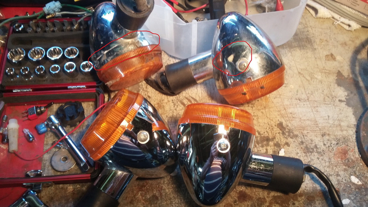 My set on top, and the replacements I found cheaply on the bottom. Seems that one turn signal mounted firmly to the fairing, and the other was still loose and could rotate. Seems strange. But once it's mounted to the fairing bracket, it wont rotate any more.  I cut the cig adapter off my volt/temp/clock on the dash, and threaded it through the air intake in the IS, through the bike, to where I want to mount a switch, so I can control the accessory ports I'm going to mount on the bike (cig/USB/volt meter).  Plug in the turn signals, head lights, replace the bolts and the screws. Did you know that the screws for the fairing are a bolt and washer, not a bolt with a shoulder?  Going to put the windshield back on, and thought I would clean it where it meets up with the mount, easier now than after it's mounted. Applied some polish, and rubbed, and noticed that what I thought was an accumulation of "stuff" was actually grooves in the windshield. Seems some of the squeaking noises I've heard from the fairing and I thought was something needing tightening, was the windshield. There still might be more, but this is quit bad, from one side to the other.  And that is pretty much another day working on my bike. |
|
|
|
« Last Edit: April 20, 2019, 05:04:07 PM by gordonv »
|
 Logged
|
1999 Black with custom paint IS   |
|
|
gordonv
Member
    
Posts: 5766
VRCC # 31419
Richmond BC
|
 |
« Reply #30 on: April 27, 2019, 04:39:02 PM » |
|
After spending 2 hours on the throttle cable and getting nowhere, I moved things around and found that spare GW GL1500 rear wheel I had sitting around. Ohhh, I needed the dampener plate for my spare Valkyrie rear wheel which I have the Austone Taxi Tire on. Dug out my Gary's Dampeners, got the plate and mounted them in the rim. Went looking for my spare brake rotors, WHERE the hell are they?? I'm really missing my mind.  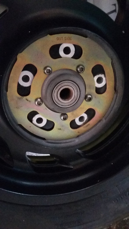 I'm forgetting where things are, I only have about 4 locations to look for them in, but I've currently lost my replacement center cover. Don't know where the bolts are, along with the seat latch lock, alt cover, and some other things. I did look somewhere else, and did find the cover bolts, and the lock. Well back to the GW rim, remove the brake rotor, and mount it onto the Valkyrie's. FYI, this was mentioned before, some parts are compatible between the GW and Valk. I didn't try the dampeners, since the GW was 2 parts and I had my last set of Gary's, but they supposedly will fit, dampener plate, bolts for plate and rotor, and the rotor. The rear rotor was light. I just hope it aligns in the brake caliper, or I'll be swapping things over from my IS rear rim.  Messed with the CC again. Got to the point that I need to hit the store and buy the pieces I've been avoiding, the vacuum canister. The wires I figure I can do after the bike is back together and running. I'll also need to make a mounting plate for the switches. I figure I'll water proof it with clear nail polish, instead of silicon, it can be cleaned off if in the future I ever need to. So I tried to start the bike again (turn it over), and after being on the charger for a week and saying fully charged, again I get a click only from solenoid, just like with a low battery. Can't get a second one unless I turn off the ignition and press it again. Pulled the light fuse, no difference. Added on my LiPe battery, which is supposedly charged, and nothing different. Now I'm going to need to pull a working car battery and carry it into the garage so I can try to jump start my bike.  Someone suggested a different charger, so I'll try that too.Can someone say New Battery? I really need to finish something, and move on to the next, but I have so many things that need doing, and only a month away from June, from vacations and Valhalla Rally. Oh well, take a deep breath and wait for another day. Left for the store and bought the items I needed. I'll try to make the vacuum canister after work one day, so I can get it to the bike and mounted. |
|
|
|
« Last Edit: April 30, 2019, 07:04:00 PM by gordonv »
|
 Logged
|
1999 Black with custom paint IS   |
|
|
gordonv
Member
    
Posts: 5766
VRCC # 31419
Richmond BC
|
 |
« Reply #31 on: April 29, 2019, 03:55:19 PM » |
|
I spent some time at work today (more tools) and cut/drilled the ABS 2" pipe to make the vacuum canister for the CC. 6" x 2" pipe, with 2 end caps, squeezed all the way on.  Couldn't find the JB Weld I thought was at home, so will wait till I'm back at the shop and look there for it. I wonder if I could use epoxy or the black ABS glue to seal up the brass vacuum nipples. But unknown how well they would seal. I've some nice commercial 3M sealant at work, but thought I would stay with what has worked (plus it's red, and I went black on the ABS). I found my JB Weld. Tried to open the used containers, and the hardener cap was stuck on. I had to pry it off. So if you are running around with a used container of JB Weld, be aware you may not be able to open it on the road when you need it. I took the brass fittings out, and JB Welded them in. Went looking for some MEK to add to my black ABS glue since I left the top off and it had mostly dried out. But the Major hardware store doesn't carry it. I'll need to look around. No one sells black ABS glue in Canada, only the yellow. I should have done this a year ago. I took those vacuum check valves out, seems they are 3/16" lines, which doesn't fit the 1/8" line for the CC actuator and the rest of the bike uses. Now I need to figure out how to take the 1/8" lines from the intake runners, and get it to the 1/8" brass nipples on the canister. Easier to see if they have 1/8" check valves. Oh joy, more figuring out to be done. |
|
|
|
« Last Edit: April 30, 2019, 08:29:10 PM by gordonv »
|
 Logged
|
1999 Black with custom paint IS   |
|
|
gordonv
Member
    
Posts: 5766
VRCC # 31419
Richmond BC
|
 |
« Reply #32 on: April 30, 2019, 07:37:40 PM » |
|
I was messing with the throttle again. Decided to remove the throttle lock. Unfortunately it uses SAE Allan screws on the handle bar clamp, and I have metric where I'm working. So thought I would try to remove what I could, take the grip off and remove the clamp. Couldn't get the end cap to unscrew. It does screw on/off, doesn't it? I suppose I'll need to find my spare and look it over. The throttle lock is a M.E. Supervista  Between that and the heated grips, I wonder what amount of fun I'll have in such a simple endevour. Again, move on to something else. I removed the throttle cables again. Got the pull chain cut to length for the CC, adjusted the slack, and all seems well. Added the vacuum line to the actuator, routed it to where I think I'll be mounting the canister. I'm not showing much on this, since there is already the how-to in the Shoptalk, and nothing much is different from that. Went back to the throttle cables, adjusted the pull cable nuts to loosen and make it easier to get the cable on. Instead of getting the pull one on also, and adjust them both, I tried out the throttle, and it snapped back. What the heck? Played with it some more, got the push cable on, tighten it up, and tried it again. The throttle is working?? What the! OK, if I've figured this out properly, it seems that I had over adjusted the pull slack, and it was pulling the whole time. I didn't do anything else, but loosen it right off. Needed to go back and adjust as per the manual. At least now the throttle snaps back like it should. I had placed the 10A battery charger on the bike when I arrived, so it was charging for about 1 hour. I had gone to the effort of removing the ground from the engine, cleaned it up (wasn't dirty at all) so everything was shinny metal, turned on the ignition and tried the starter. The engine turned over like it should have. Tried throttle, then chock, but nothing. I figure these isn't enough fuel left in the carbs, but it did almost sound like it was coughing a little. Might throw some fuel in each carb to insure I have spark, and the engine will run after I get it back together. Maybe I can use a squirt bottle, and let some fuel down the fuel hose, so it'll fill each carb. |
|
|
|
« Last Edit: June 27, 2020, 04:35:34 PM by gordonv »
|
 Logged
|
1999 Black with custom paint IS   |
|
|
gordonv
Member
    
Posts: 5766
VRCC # 31419
Richmond BC
|
 |
« Reply #33 on: May 02, 2019, 06:37:09 PM » |
|
After looking everywhere for some MEK to melt down my ABS black glue, I went to the Plastic Store, and found it there. Paid a premium for it, also only sold in a 1L container (over a quart) for $17. Would have been cheaper to buy some more glue, but black is not available in Canada anywhere I looked for it. Poured some into my glue, let it sit, stirred, shack, stirred some more, and finally glued the end caps of the vacuum canister. It was very thick, but it worked. Seems to be leak proof. Bought more vacuum items. Hose, reducers and some hose. Looks like I'm ready to mount it now, just need to wait for Sat and working on the bike again. I bought some $1 store clear nail polish, and coated the CC control switch circuit board, to water proof it. What happens, a big drop dripped right on the contact pad for the switch. Now I need to use the cleaner to expose it. One reason I wanted to use nail polish, it can be removed easily.  Just wondering if I should seal the rubber pad to the face of the cover. Na! |
|
|
|
|
 Logged
|
1999 Black with custom paint IS   |
|
|
gordonv
Member
    
Posts: 5766
VRCC # 31419
Richmond BC
|
 |
« Reply #34 on: May 12, 2019, 09:01:18 PM » |
|
I spent the day trying to get the bike to run, and other small items. Played with the petcock on the tank. Seems to work fine when not on the bike. Used a vacuum pump, 5 psi and the petcock allowed fuel to flow. Off was working. No dripping. Then why am I not running out of fuel when turned off on the Hwy???? Who cares, I'll worry about that later if there is ever a problem. I've a rebuild kit, a spare petcock, a manual petcock off a Shadow, I'll just carry them all on my trips, they're small. Getting the tank back on, a lot of fun. Placed it in position, with the recommended 4x2 under the end to keep it lifted and room to work. Plugged in the fuel sender gauge, lowered the tank. Looked for and had to reroute the fuel line to where it would meet the petcock, but couldn't get a grip on it to mount. Removed the left side engine hanger, made a big difference. Then the vacuum line from #6 to the petcock, again, had to route it, but the wire harness connectors from the ignition switch where all in the way. GRRRRR! it was not easy. No where to move the wires, but needed to, finally got the line on, then realized I needed to try to start the bike before finish mounting the tank. Pulled the vacuum line off the tube, sucked on it to open up the petcock and turned it on, hopefully letting fuel into the carbs. Back on the intake tube. Powered up the bike, enricher, crank and crank, and she fired up (with no exhaust pipes, kind of loud). Let it idle till the rpms started coming up, then turned it off and left the enclosed garage as fast as I could to let it air out the exhaust gases. Had lunch with mom.  Buttoned up the rest of the tank, bid back on, bolted down. Boy was that tank ratty under the bid. I think I have a pic on the camera I tried using, will post later. Added on the cig accessory plug with USB outlets, back at the top/neck of the bike, where it was before. Had forgotten this one, as I should have routed the wires under the gas tank, so I did the usual thing, and ran then along the side, and pulled the wire till it tightened up under the edge of the tank, threaded it through the wire loom to the battery. I really wished I could remember where the hell I put the add on fuse box I bought. I wanted to wire it in using a relay and trigger it from the accessory power on the right side of the IS. Plug in all the extras I have, volt meter, access ports, CC, heated gear outlets, what else? Oh, I bought one of those front/back dash cams. That will be one of the last things added on, most likely next year, but I want it asap. Next, get the center cover in, tilt back on, seat lock back in and working. This will be fun, but I've done it 3 times recently. Figure it should be easier now. But first, fix the new replacement cover (since I couldn't find the one I had, I bought another which was missing a tab). 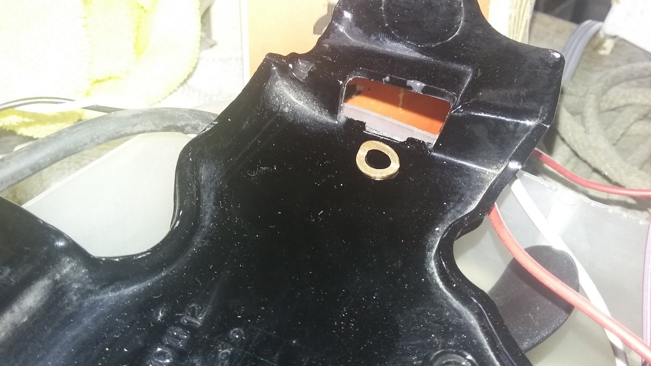 Got a small dia washer, bent it 90', and it brakes. Find another one, copper this time, bend, looks good. Now for the fun. Place it in position, take out the soldiering iron, and melt it into the ABS plastic of the cover. Now only half way through, being careful not to have anything show through to the good side. Cool it down. Now pull out the ABS glue I fixed up. Using a tooth pick, applied a nice thick layer over the washer and area around to support it.  I was going to cover the whole washer with ABS plastic, but after trying it out (before gluing it down) and verifying it works, I felt there was no reason to play with it anymore. Just to get it firmly mounted should be fine. Now to see how long it lasts. I expect forever, as how often do you take off the side covers? So next week, in it should go. Then the next stage of fun begins. Remove my single piece trailer hitch, and replace with the 3 piece one, so I can get the rear fender off, and mount my replacement (now obsolete) ATT tire and black powder coated rim. Then wire in the replacement 5/4 wire connector for the trailer. This will be the 3rd one. They seem to fail in one season. Fun - Fun - Fun. |
|
|
|
« Last Edit: June 27, 2020, 04:56:47 PM by gordonv »
|
 Logged
|
1999 Black with custom paint IS   |
|
|
gordonv
Member
    
Posts: 5766
VRCC # 31419
Richmond BC
|
 |
« Reply #35 on: May 13, 2019, 03:31:08 PM » |
|
I thought a good time to look at my CB and see if I can mount it under the trunk, where it belongs on the IS. Unpackaged it, and noticed that the leads are short. Sure, its from the Yamaha, but I thought it was suppose to have 3' long leads?  Well at least the connection to the radio was long enough to reach from the compartment behind the battery. Hmmm, how long is that radio connection, I'll need to verify, see if it might fit from the trunk, with the radio portion running towards the back. Good thing I bought a mix bag of connectors. I've the ones I need to make an extension for the power. Tried the connector and made sure it would fit the OEM ones. |
|
|
|
|
 Logged
|
1999 Black with custom paint IS   |
|
|
gordonv
Member
    
Posts: 5766
VRCC # 31419
Richmond BC
|
 |
« Reply #36 on: May 18, 2019, 06:28:05 PM » |
|
It seems nothing could cover this mess,  But the original single pouch bib. The Iron Horse 2 pocket one wouldn't cover it, you could see the mess under it, so back on the original one pocket. I rolled the bike outside, where I could get around to the rear of it, so I could remove the single piece chrome trailer hitch, for the 3 piece one I bought, so I could remove the rear section and change my own rear wheel. But first, from all the reading I looked over about mounting a hitch, I was going to remove the trunk, so I need to unplug the trunk. So track the wires/cable going to the back, and what do I need to deal with, all this "stuff" from the PO.   Ones the CB plug for the passenger, another for the rear speakers, then there should be the rear lights and the trunk lights, but what is this extra one going into the fender? It doesn't jive with what I know it should be like. Will have to research what it's for. Then this collection of Vampires feeding on my wiring. I'm thinking it might be easier to buy some new wire harnesses. I already have the Std/Tourer fender wires, harness A & B, so I can mount the fender brake light. So a new wire harness for the trunk looks like it might be in my future.  Will mean starting from scratch for installing the wire harness for the trailer. But then I can add in a Y split for the trailer, not having to cut into the wires there. I notice that there doesn't seem to be bolts holding the trailer hitch on, but studs. I suspect someone did it right when they mounted the one piece hitch. So I took the saddle bags off, but I have guards on, they needed to be removed (expanded) to allow the reflector pass and remove the bags. The rear pipe support for the saddle bags came off. I wonder why my bike has so many rattles? ???  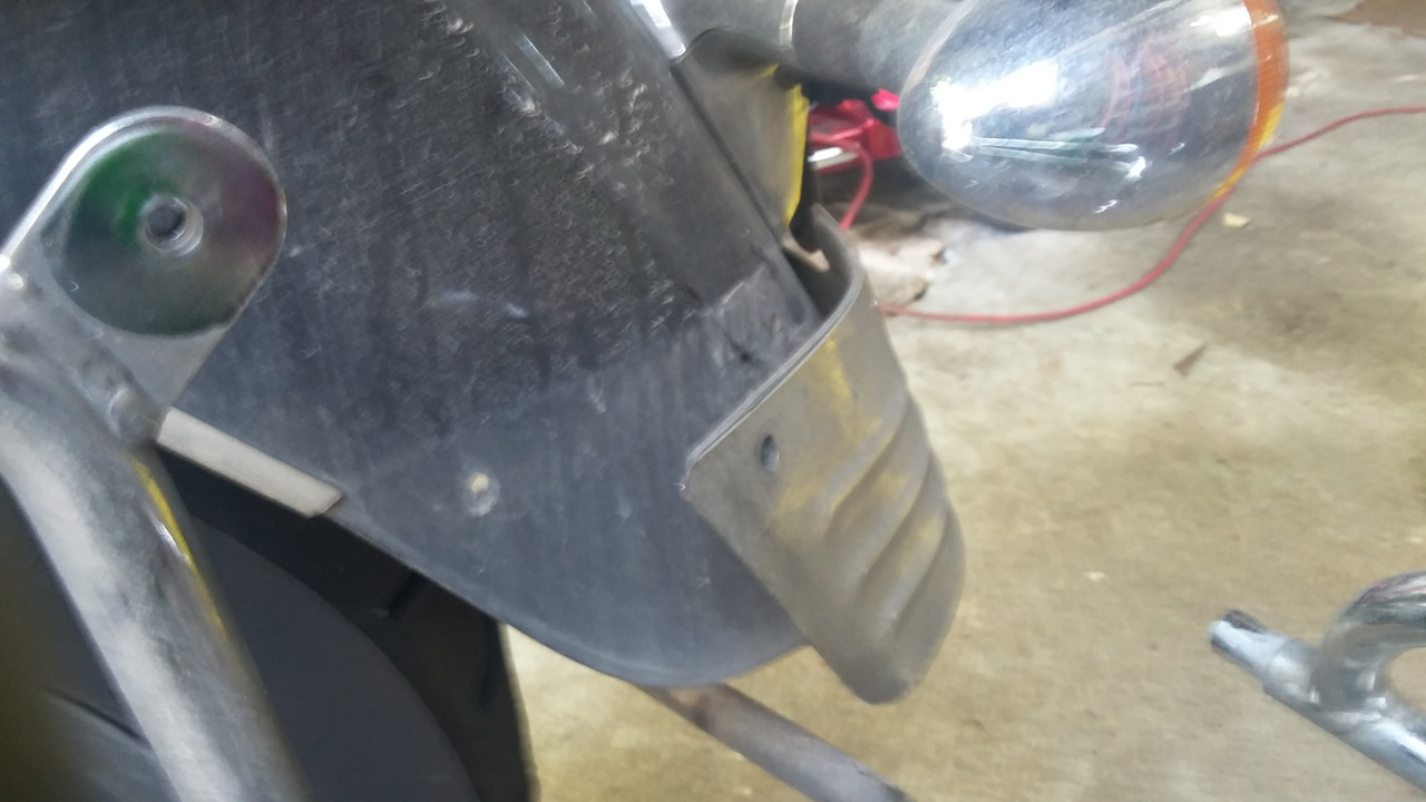 Seems out of 4 bolts/nuts, there was only one holding it on. So off it came, until I can figure a way of mounting it. Either the shouldered bolts or something else, but all matching. Remove the nuts from the studs, pry the hitch wide and off them, and out it came.  The 3 piece has L on the one side, so on they went, then the rear piece, tighten it all up and the pipe and rear guard back on.  My bike had the license plate reflectors cut off,  I didn't like how it was done, along with safety items remove, so bought one for $10 and put it on. Easy peasy.  I rechecked the wire length for the CB, and unless I can get an extension for the connector, I'll need to mount this at the battery box. I got the two inner fairings back on. The right side was easy. Mounted the sensor for the head light modulator, the speakers, and back on it went. The left side, speakers, then the wires for the heated grip power light and mount the on/off switch. On it goes. Before I left, I remembered to try the heated grips, and they aren't working. Good thing it's summer, but I think the fairing needs to come off again and trace those wires and see why. But I don't have many weekends left, and a lot of OT at work, so will need to wait for another time. |
|
|
|
« Last Edit: May 18, 2019, 07:30:27 PM by gordonv »
|
 Logged
|
1999 Black with custom paint IS   |
|
|
|
Chrisj CMA
|
 |
« Reply #37 on: May 19, 2019, 04:10:36 AM » |
|
I have the Hitch Doc chrome single piece hitch on the bike and have no problem removing the rear wheel myself. I don’t have a center stand so I would need a lift either way but with the lift I never have to remove the fender
|
|
|
|
|
 Logged
|
|
|
|
gordonv
Member
    
Posts: 5766
VRCC # 31419
Richmond BC
|
 |
« Reply #38 on: May 19, 2019, 11:02:54 AM » |
|
I have the Hitch Doc chrome single piece hitch on the bike and have no problem removing the rear wheel myself. I don’t have a center stand so I would need a lift either way but with the lift I never have to remove the fender
A lift would be great, even to just get a good work height. I've the center stand, and one thing I like the idea of, is to have the ability to remove my wheel while away from a shop, or any other rear end service. I've never removed the rear fender yet on a bike (except for the mc dismantle I did 8 years ago now), and will be my next job, swapping out my rear wheel to the Austone I have mounted, with the double roller bearing mod. Then changing the wire harness to the Std/Tourer. The other minor reason is, the ability to remove the trailer hitch ball, via the pin. |
|
|
|
|
 Logged
|
1999 Black with custom paint IS   |
|
|
gordonv
Member
    
Posts: 5766
VRCC # 31419
Richmond BC
|
 |
« Reply #39 on: May 19, 2019, 12:21:07 PM » |
|
I added the circles for the wires going through the front section of the rear fender.  I have been unable to find any information anywhere about the second set of wires, that has gone through a rubber grommet at the rear of the fender (the left circled one). I figure I wont know what this is for, until I remove the rear wheel and get the fender apart. There is no hole in any fender I looked at on ebay. There is no routing of this extra wires in the service manual. Nothing on pics I found of the fender. Nothing I found in wiring diagrams. I suspect with the condition of my wire harnesses, that this is a bypass of broken wires to the rear fender lights. So again, with a replacement of the sub harnesses A & B, I'm likely to clean up more than just a visual mess. Without another IS on hand, I'm unable to pull up the seat and look over what is there OEM. Oh Boy! More work, more research, more figuring out, WTF!!!  And no time to do it in. |
|
|
|
|
 Logged
|
1999 Black with custom paint IS   |
|
|
|

