MarkT
Member

Posts: 5196
VRCC #437 "Form follows Function"
Colorado Front Range - elevation 2.005 km

|
 |
« Reply #40 on: March 19, 2018, 06:44:54 PM » |
|
If you tap the power for the panel off the dogbone - which is a 55 amp fusible link - you will protect from a disastrous short. Meanwhile every circuit downstream is fused much smaller so they will blow from the local short before the dogbone blows. I have wired mine this way - no chance my bike is going to burn up from an electrical fire. One buss on my PC-8 is unswitched and the smaller one is switched. All of the circuits have their own switching anyway, which depends on the condition needed. I have one circuit that is powered ONLY when the ignition is off. Uses the 87a terminal of an ignition switched relay. That circuit is for the solenoid that opens the valve to dump the main tank fuel to the belly, at the gas pump. It's switched back off when the ignition is activated. I have a red LED warning me I'm using power with the engine off. It's actually a pretty low draw, just a bit more than a Dan-Marc.
|
|
|
|
|
 Logged
|
|
|
|
|
mark81
|
|
« Reply #41 on: March 19, 2018, 06:49:27 PM » |
|
When I bought my bike there was an aux fuse box installed. the headlight wiring was re routed to trigger a relay to power fuse block. there was a 30 amp inline fuse going to the fuse block. Run off of that fuse block was the
headlight 5.4a
spot lights on the light bar 9.2a
fog lights on the crash guard 9.2a
air horn 16a
grand total 39.8 Amps
long story short 30 amp fuse and holder powering the fuse block melted and I had no lights at all going home at 10:30pm. make sure your wiring is enough to handle the expected load. air horns draw a lot of current.
|
|
|
|
|
Logged
|
1997 Honda Valkyrie 1981 Honda CB750 Custom  |
|
|
|
Bigwolf
|
|
« Reply #42 on: March 20, 2018, 11:28:37 PM » |
|
When I bought my bike there was an aux fuse box installed. the headlight wiring was re routed to trigger a relay to power fuse block. there was a 30 amp inline fuse going to the fuse block. Run off of that fuse block was the
headlight 5.4a
spot lights on the light bar 9.2a
fog lights on the crash guard 9.2a
air horn 16a
grand total 39.8 Amps
long story short 30 amp fuse and holder powering the fuse block melted and I had no lights at all going home at 10:30pm. make sure your wiring is enough to handle the expected load. air horns draw a lot of current.
When I installed my PC8 and cleaned up the rats nest of wires on my bike, I ran one completely separate circuit for my headlight. That circuit does not go through the PC8 but comes directly through a 20 amp automatic resetting circuit breaker and 30 amp relay and runs directly to the headlight. My driving lights are on the PC8. This way, I have forward lights unless the whole electrical system goes down. I have had the lights go out at speed on twisty mountain roads...........did not care for the pucker that caused in a car and for sure do not want to experience that on 2 wheels. I have photos of my set up but do not currently have a way to get them uploaded here. I have several relays and all of the fuses under the right side panel. It is done in 2 layers with the first layer being a hinged board with the PC8. That board can be lifted up to access the relays, dog bone, starter solenoid, ETC. Bigwolf |
|
|
|
|
Logged
|
|
|
|
|
Motodad71
|
|
« Reply #43 on: March 27, 2018, 09:16:32 PM » |
|
Another Easternbeaver fan, have a PC8 on my V-Strom and it’s worked flawlessly. Am I to assume headlight relay is installed to take the high current draw off the stock wiring, and may I also assume the extra juice makes the headlight a bit brighter?
|
|
|
|
|
Logged
|
1997 yellow/black Valkyrie standard "Thor"
|
|
|
|
Harryc
|
|
« Reply #44 on: March 28, 2018, 05:59:18 AM » |
|
Another Easternbeaver fan, have a PC8 on my V-Strom and it’s worked flawlessly. Am I to assume headlight relay is installed to take the high current draw off the stock wiring, and may I also assume the extra juice makes the headlight a bit brighter?
Correct, you got it. |
|
|
|
|
Logged
|
|
|
|
|
Motodad71
|
|
« Reply #45 on: April 02, 2018, 02:23:35 PM » |
|
So....for any of you who are using the Eastern Beaver PC-8, which kit did you go with "like 24" kit" and where did you mount it, and what are you using as the switched power for the switching lead? I am also looking at his single H4 headlight relay kit as well, have the dual kit on My V-Strom.  |
|
|
|
|
Logged
|
1997 yellow/black Valkyrie standard "Thor"
|
|
|
|
Harryc
|
|
« Reply #46 on: April 02, 2018, 03:06:35 PM » |
|
Not using that kit, and am making my own relay harness, but the switched trigger is easy to answer. There is an unused accessory circuit that can be accessed under the right side cover (Standard and Tourer) It's also fused so no worries there. If you have an Interstate, i don't know.
|
|
|
|
« Last Edit: April 02, 2018, 03:11:25 PM by Harryc »
|
Logged
|
|
|
|
|
Bigwolf
|
|
« Reply #47 on: April 03, 2018, 01:25:44 PM » |
|
Not using that kit, and am making my own relay harness, but the switched trigger is easy to answer. There is an unused accessory circuit that can be accessed under the right side cover (Standard and Tourer) It's also fused so no worries there. If you have an Interstate, i don't know.
Same here. |
|
|
|
|
Logged
|
|
|
|
|
Motodad71
|
|
« Reply #48 on: April 03, 2018, 01:49:46 PM » |
|
For sure some merit in making your own, but I reckon I like units which are intentionally designed for such and sold all over the world. I love plug and play as much as possible, and I know that Easternbeaver also used some of the best components/relays and connectors available out there.
|
|
|
|
|
Logged
|
1997 yellow/black Valkyrie standard "Thor"
|
|
|
|
..
|
|
« Reply #49 on: April 03, 2018, 03:43:55 PM » |
|
Big BF wired in my PC8. Here's some of the wiring he removed that previous owners had rat nested.  |
|
|
|
|
Logged
|
|
|
|
|
Bigwolf
|
|
« Reply #50 on: April 04, 2018, 01:18:34 PM » |
|
I finally managed to get one of many photos from my phone onto my computer. Here is a photo looking at my PC8 mounted on a hinged panel under the right side cover.
I have many more of my wiring layout but cannot seem to get them to transfer to my regular email or to my old relic of a computer.
Bigwolf
Well, that didn't work either. I will keep trying.
|
|
|
|
« Last Edit: April 04, 2018, 01:37:44 PM by Bigwolf »
|
Logged
|
|
|
|
|
Motodad71
|
|
« Reply #51 on: April 04, 2018, 01:27:09 PM » |
|
|
|
|
|
|
Logged
|
1997 yellow/black Valkyrie standard "Thor"
|
|
|
|
Bigwolf
|
|
« Reply #52 on: April 04, 2018, 01:38:04 PM » |
|
 Hey! That worked. Now I just have to find a way to get the others off my phone and onto my computer so I can post the series on my electrical layout. |
|
|
|
« Last Edit: April 15, 2018, 08:14:51 PM by Bigwolf »
|
Logged
|
|
|
|
|
Harryc
|
|
« Reply #53 on: April 04, 2018, 01:42:12 PM » |
|
Very clean install, awesome job. I'm going to make a confession here, and I hope it helps someone. I spent days (and more dollars than it was worth) to design and build my own relay harness for the Centech AP-2. I finished last night but it wasn't perfect, so I don't trust it. Lets just say it's hard to manage 10 guage wire and associated connectors/soldering effectively. So I ordered the Centech factory relay harness for less money (and time) than it took to build my home made harness. Lesson learned. Same advice could be applied to the CP8. At the end of the day to spend $40 shipped for a plug and play harness is not such a bad thing.  I ride a lot of miles a year and my goal (beside perfect maintenance) is not to be 'that guy' on the side of the road. Ride on! |
|
|
|
« Last Edit: April 04, 2018, 01:53:04 PM by Harryc »
|
Logged
|
|
|
|
|
Motodad71
|
|
« Reply #54 on: April 04, 2018, 01:53:02 PM » |
|
https://postimg.org/image/5vhfap8k5/ Hey! That worked. Now I just have to find a way to get the others off my phone and onto my computer so I can post the series on my electrical layout. I'm liking that, which PC8 kit "length" did you get, and what is the hinged panel from or did you make it? |
|
|
|
|
Logged
|
1997 yellow/black Valkyrie standard "Thor"
|
|
|
|
Bigwolf
|
|
« Reply #55 on: April 04, 2018, 02:20:32 PM » |
|
Harryc,
Thanks, I try to make things neat and as trouble free as possible.
Motodad71,
I just bought the PC8 by itself. I made the harness to fit my needs and mounting location.
I bought a 1 foot piece of stainless piano hinge from hardware store. Had to cut a couple of inches off and trim it so it would do what I wanted. I will post photos when I can.
The panel board is cut from a 1/8 thick piece of 6061 T6 aluminum that I had in my junk pile. I first cut a cardboard template to fit as I wanted it and then transferred that shape to the aluminum. I would prefer a non conductive material for this panel but I would of had to buy something and I had the aluminum here. Did I mention it was in my pile of scrap to maybe use for something someday? Not sayin I am a packrat but......
I took the OEM fuse box off the side of the battery box and relocated it to the far right end of the paino hinge. There was no rewiring necessary to make that move and moving it gave room for several relays to be installed on the side of the battery box all neatly packed in there together.
Now all but 2 fuses can be accessed as soon as the side cover is removed and all relays plus the remaining 2 fuses can be accessed by lifting that aluminum panel.
I do hope to get more photos up soon. That should help to understand details.
Bigwolf
|
|
|
|
|
Logged
|
|
|
|
|
Motodad71
|
|
« Reply #56 on: April 04, 2018, 02:42:29 PM » |
|
Awesome info sir, I'm not sure how I quite want to mount my PC8 when I get it, but I sure do like what you did.
|
|
|
|
|
Logged
|
1997 yellow/black Valkyrie standard "Thor"
|
|
|
|
..
|
|
« Reply #57 on: April 04, 2018, 02:55:22 PM » |
|
https://postimg.org/image/5vhfap8k5/ Hey! That worked. Now I just have to find a way to get the others off my phone and onto my computer so I can post the series on my electrical layout. Email them from phone to PC? |
|
|
|
|
Logged
|
|
|
|
|
Bigwolf
|
|
« Reply #58 on: April 04, 2018, 07:17:59 PM » |
|
https://postimg.org/image/5vhfap8k5/ Hey! That worked. Now I just have to find a way to get the others off my phone and onto my computer so I can post the series on my electrical layout. Email them from phone to PC? Britman, I have tried that several times.........had to empty my outbox several times because they just kept stacking up there and none of them would go through. I got the one that I posted to go through but the other 20 or so just refuse to upload to my email. I will try my wife's computer sometime when she is not around. It is windows 10 and sometimes I can get it to interface directly with my phone. Bigwolf |
|
|
|
|
Logged
|
|
|
|
|
The emperor has no clothes
|
|
« Reply #59 on: April 05, 2018, 06:19:04 AM » |
|
https://postimg.org/image/5vhfap8k5/ Hey! That worked. Now I just have to find a way to get the others off my phone and onto my computer so I can post the series on my electrical layout. Email them from phone to PC? Britman, I have tried that several times.........had to empty my outbox several times because they just kept stacking up there and none of them would go through. I got the one that I posted to go through but the other 20 or so just refuse to upload to my email. I will try my wife's computer sometime when she is not around. It is windows 10 and sometimes I can get it to interface directly with my phone. Bigwolf Couldn't you just upload to post image directly from your phone ? |
|
|
|
|
Logged
|
|
|
|
|
Bigwolf
|
|
« Reply #60 on: April 05, 2018, 12:55:44 PM » |
|
https://postimg.org/image/5vhfap8k5/ Hey! That worked. Now I just have to find a way to get the others off my phone and onto my computer so I can post the series on my electrical layout. Email them from phone to PC? Britman, I have tried that several times.........had to empty my outbox several times because they just kept stacking up there and none of them would go through. I got the one that I posted to go through but the other 20 or so just refuse to upload to my email. I will try my wife's computer sometime when she is not around. It is windows 10 and sometimes I can get it to interface directly with my phone. Bigwolf Couldn't you just upload to post image directly from your phone ? Well,.....yes, apparently I can. Thanks Meathead. I have gotten really out of touch with modern technology. |
|
|
|
|
Logged
|
|
|
|
|
Bigwolf
|
|
« Reply #61 on: April 05, 2018, 01:02:13 PM » |
|
Hey Guys,
I started a new thread/post with my install and I even managed to get the photos up there too. It is titled: PC8 Install and Electrical layout. It took a lot of time, 6 hours just today, to get that post up. I sure hope it helps some of you out.
Bigwolf
|
|
|
|
|
Logged
|
|
|
|
|
Harryc
|
|
« Reply #62 on: April 06, 2018, 02:25:48 PM » |
|
Well, it might not be as pretty as some installations, but it's definitely overbuilt.  . 10ga wire, every terminal is soldered and shrink wrapped. I only have (2) wires on the battery instead of eight. 30a inline fuse on the positive battery connection. Here's what I have hooked to the Centech AP-2; Always on - Heated gear, air horn. Switched - Voltage meter and heated grips. I have an adapter for the heated gear wiring to accept a battery tender, that's why I wanted it always on. I transferred all fuses one for one for each circuit. I ran wiring for future running lights (and the volt meter direct to the battery) and I installed a dual lighted switch on the handlebars. One switch for the volt meter, and the second for the future running lights. It's mounted on a wooden box cover that fits exactly in the space under the seat behind the battery where the tool kit once was. I chose wood because it is obviously non-conductive in the event of a wire coming loose. The 30/40a relay is hard to see because it's black, but it is screwed into the side of the wooden box. It is triggered (via posi-tap) off of the 12v aux circuit found under the right side cover. That aux circuit also runs my Dan-marc, which I decided to leave alone and not move it to the AP-2. The thought process was...If the AP-2 or relay fail, at least I can still get home. In a previous thread I had some problems with the volt meter reading low because I hooked it to the front running lights in the headlight bucket. It's now running directly off the AP-2/battery....problem solved.  |
|
|
|
« Last Edit: April 06, 2018, 03:01:12 PM by Harryc »
|
Logged
|
|
|
|
|
|
|
Motodad71
|
|
« Reply #64 on: April 07, 2018, 01:11:40 PM » |
|
Like that set up Harry, very much what I am intending to do with a PC8......great solution and easily accessible.  Do you use the accessory lead to power the relay for the Centech, if not what are you using those leads for by chance? |
|
|
|
« Last Edit: April 07, 2018, 01:13:31 PM by Motodad71 »
|
Logged
|
1997 yellow/black Valkyrie standard "Thor"
|
|
|
|
Harryc
|
|
« Reply #65 on: April 07, 2018, 07:39:29 PM » |
|
Like that set up Harry, very much what I am intending to do with a PC8......great solution and easily accessible. Do you use the accessory lead to power the relay for the Centech, if not what are you using those leads for by chance? Thanks! Yes I am using the accessory lead to power the trigger on the relay for the Centech. |
|
|
|
|
Logged
|
|
|
|
|
Bigwolf
|
|
« Reply #66 on: April 08, 2018, 06:58:39 AM » |
|
Well, it might not be as pretty as some installations, Harryc, Pretty is not really all that important. What works well and lasts a long time is what I believe to be important and you seem to have that covered. I am curious about the green and yellow wires by the negative post of the battery though. Cannot tell by the photo if vibration could cause the insulation to get worn and cause a short there. Probably just the way I am seeing it in the photo. Bigwolf |
|
|
|
|
Logged
|
|
|
|
|
Harryc
|
|
« Reply #67 on: April 08, 2018, 08:00:32 AM » |
|
Well, it might not be as pretty as some installations, Harryc, Pretty is not really all that important. What works well and lasts a long time is what I believe to be important and you seem to have that covered. I am curious about the green and yellow wires by the negative post of the battery though. Cannot tell by the photo if vibration could cause the insulation to get worn and cause a short there. Probably just the way I am seeing it in the photo. Bigwolf Good eye. I ran a (4) wire harness from the battery area up to the front of the bike. I'm not currently using the green/yellow wires though. They are just tucked away for future use (plan on installing running lights). Once they are live I'll be sure to keep them away from chafing. The other (2) wires in that harness (white and black which you can see hooked up to the fuse panel) run up to a 2 position lighted switch on the handlebar and eventually to a Koso volt meter up on the triple tree. I can switch the volt meter on and off with the switch. The other unused switch position will be used for the future running lights. Both of those circuits are and will be on 'switched' circuits on the panel, so with the key off they are off as well. I like to plan ahead...makes life easier down the road. |
|
|
|
« Last Edit: April 08, 2018, 08:17:13 AM by Harryc »
|
Logged
|
|
|
|
|
Bigwolf
|
|
« Reply #68 on: April 08, 2018, 08:22:37 AM » |
|
Well, it might not be as pretty as some installations, Harryc, Pretty is not really all that important. What works well and lasts a long time is what I believe to be important and you seem to have that covered. I am curious about the green and yellow wires by the negative post of the battery though. Cannot tell by the photo if vibration could cause the insulation to get worn and cause a short there. Probably just the way I am seeing it in the photo. Bigwolf Good eye. I ran a (4) wire harness from the battery area up to the front of the bike. I'm not currently using the green/yellow wires though. They are just tucked away for future use (plan on installing running lights). Once they are live I'll be sure to keep them away from chafing. The other (2) wires in that harness (white and black which you can see hooked up to the fuse panel) run up to a 2 position lighted switch on the handlebar and eventually to a Koso volt meter up on the triple tree. I can switch the volt meter on and off with the switch. The other unused switch position will be used for the future running lights. Both of those circuits are and will be on 'switched' circuits on the panel, so with the key off they are off as well. I like to plan ahead...makes life easier down the road. |
|
|
|
|
Logged
|
|
|
|
|
Gental Gaint
|
|
« Reply #69 on: April 15, 2018, 05:02:19 PM » |
|
|
|
|
|
|
Logged
|
Raymond Johnson
Houston/Richmond, Texas
"Live Life"
Cell: 281-460-3794
I will ride with anyone... let's go....
|
|
|
|
Leathel
|
|
« Reply #70 on: May 02, 2018, 09:41:25 PM » |
|
mmmm sometimes it pays not to read posts when you are busy....it seems I need a PC8 now so more to do in my "spare" time  They look good, I might have to go down that road, it would look tidier, when time permits |
|
|
|
|
Logged
|
|
|
|
|
BobB
|
|
« Reply #71 on: May 04, 2018, 03:44:50 PM » |
|
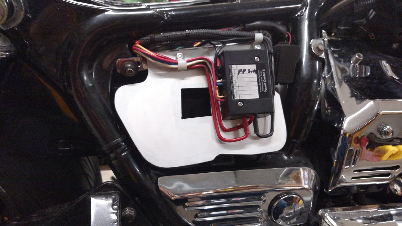
I installed a PC-8 4+ years ago after seeing a similar installation at Inzane XIII. 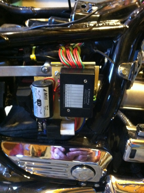 |
|
|
|
|
Logged
|
|
|
|
|
Bigwolf
|
|
« Reply #72 on: May 05, 2018, 11:04:42 AM » |
|
Very nice install BobB
|
|
|
|
|
Logged
|
|
|
|
|


