Earlier this year I scored a set of OEM H-D LED spotlights at a price I simply couldn't pass up. Shortly thereafter I got hold of one of their OEM projector headlights, also for a price I couldn't refuse.
I'd had Josh's bracket on-hand for a while, and decided to give the installation a go on my Tourer. Mechanically, once things fell into place the headlight installation was straightforward - as was the spotlight install. Aiming was done empirically and once I had things dialed in I was
very impressed with the results.
That is, until I turned the bike's radio on. FWIW, this is the Hondaline (Clarion) CB which is connected to a Kennedy FRSet4 integrator, allowing the dual-band ham rig I have on the bike to utilize the Hondaline mic audio for transmitting. In receive, the ham rig's audio is routed to the CB's Line In connection - allowing me to hear both and transmit on either.
All worked fine with the stock incandescent headlight and spots. The LED units put out so much RFI that the squelch had to be turned all the way up to mute the CB receiver. I'm guessing on the order of 200uV or more RF energy at 27MHz, though I didn't put the lights on my spectrum analyzer to verify.
I ended up diving back into basic electronics theory and turned to my old friend the Pi filter. It's an effective EMI suppressor. The headlight current draw was measured (~3A each for low and high beam) and a bunch of 100uH, 6A toroid chokes were obtained. These are 13mm in diameter and 8mm thick - small enough to mount inside the headlight casing with the other electronics.
The other components used are 100uF, 35WVDC electrolytic capacitors. One inductor and two capacitors are used on each "beam" connection; the feeds to the PWM controller board were unsoldered and the filters inserted there.
Schematically:
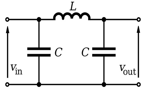
"VIn" is the supply side connection, "VOut" is the feed to the headlight's controller board and "Ground" (the common line at the bottom) is the PWM board's ground connection. The (+) terminals of the capacitors go to the inductor (In and Out side) while the (-) goes to Gnd. I chose to mount the components inside my light to positively suppress EMI at its source. This can be a dicey job, so familiarity with reworking or modifying such circuitry is a foregone conclusion.
The results...turn the CB on without the light connected. Unsquelch it and listen to the background noise. Plug the headlight in - the ambient level barely changes. Activating the High beam (which turns on all the LEDs in my particular light) generates a little more noise but signals which were at the noise level are still readable. Without putting a scope and analyzer on the setup, I'm betting the total noise increase with the filtering in place is less than 1uV - probably close to 0.2.
The same circuit was applied to the spotlight feeds, albeit externally - there's no way to open the cases. I was able to get their combined noise level down to roughly 30-40uV - equivalent to setting the radio's squelch to "10" before quieting is achieved. More work in this area to follow.
I'll post a pic of the modified PWM board if anyone's interested.


