Dragunslayer
Member

Posts: 236
"AN APEX IS A TERRIBLE THING TO WASTE"
Robertsville, MO
|
 |
« on: June 04, 2023, 07:09:01 PM » |
|
Honestly I do not know what my problem is LOL. So with the help of some great members on this site I was able to wire up my driving lights and use the factory OEM switch to trigger them when switching to the highbeam. Problem is now I am adding an air horn and no matter how I wire the relay it will not trigger the airhorn thru the switch. Short answer is yes I have checked to verify that the switch is functioning properly. Any help would be greatly appreciated once again I have tried multiple different diagrams with no success.
|
|
|
|
|
 Logged
|
Kevin Reinhold AKA Dragunslayer
Robertsville, Mo
1999 Honda Valkyrie Tourer
2015 Kawasaki Concours 14
2016 Suzuki GSXS-1000F
"AN APEX IS A TERRIBLE THING TO WASTE"
|
|
|
|
Mooskee
|
|
« Reply #1 on: June 04, 2023, 07:58:39 PM » |
|
This will do it. You MIGHT not need the Flyback Diode in this case, I just always use them. It keeps an inductive kick from the collapsing coil from damaging anything in the path. There isn't really any sensitive electronics in the path of the horn circuit. 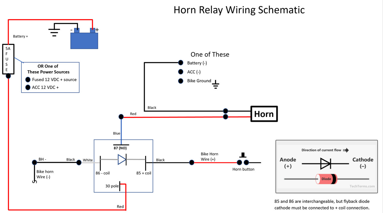 |
|
|
|
« Last Edit: June 04, 2023, 08:02:52 PM by Mooskee »
|
Logged
|
|
|
|
Dragunslayer
Member
Posts: 236
"AN APEX IS A TERRIBLE THING TO WASTE"
Robertsville, MO
|
|
« Reply #2 on: June 04, 2023, 08:23:06 PM » |
|
This will do it. You MIGHT not need the Flyback Diode in this case, I just always use them. It keeps an inductive kick from the collapsing coil from damaging anything in the path. There isn't really any sensitive electronics in the path of the horn circuit. I will give this a try and let you know how it goes. Have I stated how I hate wiring LOL |
|
|
|
|
Logged
|
Kevin Reinhold AKA Dragunslayer
Robertsville, Mo
1999 Honda Valkyrie Tourer
2015 Kawasaki Concours 14
2016 Suzuki GSXS-1000F
"AN APEX IS A TERRIBLE THING TO WASTE"
|
|
|
|
RonW
|
|
« Reply #3 on: June 04, 2023, 11:39:21 PM » |
|
Have you tested the airhorn (orange rectangle)? If you have the horn off the bike, you can place the horn next to the battery so you don't need long jumper wires.  |
|
|
|
|
Logged
|
2000 Valkyrie Tourer
|
|
|
Dragunslayer
Member
Posts: 236
"AN APEX IS A TERRIBLE THING TO WASTE"
Robertsville, MO
|
|
« Reply #4 on: June 05, 2023, 07:11:45 PM » |
|
So the horn is brand new and yes the horn activates it just will not activate with the relay as a trigger. I tried using the diagram that is provided in this thread with no luck. Tried switching wires coming from the switch to the relay is far is 85 and 86 are concerned with no effect.
By the way I have several relays and have tried several different relays to make sure that it is not a related issue as well. I’m about ready to just put a regular horn on LOL
|
|
|
|
|
Logged
|
Kevin Reinhold AKA Dragunslayer
Robertsville, Mo
1999 Honda Valkyrie Tourer
2015 Kawasaki Concours 14
2016 Suzuki GSXS-1000F
"AN APEX IS A TERRIBLE THING TO WASTE"
|
|
|
Willow
Administrator
Member

Posts: 16758
Excessive comfort breeds weakness. PttP
Olathe, KS

|
|
« Reply #5 on: June 05, 2023, 07:31:20 PM » |
|
Check where you placed the relay. It has to be on the power side. The switch, honestly, will work on either the power or ground side to complete the circuit. The relay is not that forgiving.
|
|
|
|
|
Logged
|
|
|
|
Dragunslayer
Member
Posts: 236
"AN APEX IS A TERRIBLE THING TO WASTE"
Robertsville, MO
|
|
« Reply #6 on: June 05, 2023, 08:09:48 PM » |
|
Not sure that I understand what you are saying regarding the power side of the relay?
|
|
|
|
|
Logged
|
Kevin Reinhold AKA Dragunslayer
Robertsville, Mo
1999 Honda Valkyrie Tourer
2015 Kawasaki Concours 14
2016 Suzuki GSXS-1000F
"AN APEX IS A TERRIBLE THING TO WASTE"
|
|
|
Willow
Administrator
Member
Posts: 16758
Excessive comfort breeds weakness. PttP
Olathe, KS
|
|
« Reply #7 on: June 05, 2023, 08:19:45 PM » |
|
Not sure that I understand what you are saying regarding the power side of the relay?
I don't know how I can say it more clearly. A switch completes a circuit form power to ground. It works just as well on the power or the ground side of the circuit. A relay reacts to the power side of the circuit only. The object being triggered (the horn in this case) can be on either the power or ground side of the switch. |
|
|
|
|
Logged
|
|
|
|
Dragunslayer
Member
Posts: 236
"AN APEX IS A TERRIBLE THING TO WASTE"
Robertsville, MO
|
|
« Reply #8 on: June 06, 2023, 05:01:56 AM » |
|
So I have the relay powered by a 30 amp thermal fuse connected to the the battery.I have the two wires coming from the switch on the handlebar which have NO color indications but have been checked that they complete a circuit when the button is pressed. Those wires in the last scenario were connected to 85 and 86 on the relay 30 going to the thermal fuse and last but not least the positive side of horn is connected to 87 on the relay. The ground for the horn was grounded to negative on the battery.
Not sure if this helps you tell me whether or not I am wired in the correct order that you are trying to describe. All I can say is that the relay is in the middle between the switch and the horn. In theory when I press the button this should complete circuit between 85 and 86 sending power to 87 correct?
|
|
|
|
|
Logged
|
Kevin Reinhold AKA Dragunslayer
Robertsville, Mo
1999 Honda Valkyrie Tourer
2015 Kawasaki Concours 14
2016 Suzuki GSXS-1000F
"AN APEX IS A TERRIBLE THING TO WASTE"
|
|
|
Skinhead
Member
Posts: 8742
J. A. B. O. A.
Troy, MI
|
|
« Reply #9 on: June 06, 2023, 05:28:27 AM » |
|
If I read your last post correctly, your problem is you have both of the wires from the switch attached to the relay, which in essence means there is no power source to the switch. One wire going to the switch has to provide power, the other should go to the coil of the relay, and then the other terminal from the coil relay should be grounded. When you activate (close) the switch, the coil will be energized and pull the load side contacts of the relay closed. What you have done is essentially this:  |
|
|
|
|
Logged
|
 Troy, MI |
|
|
|
Timbo1
|
|
« Reply #10 on: June 06, 2023, 07:51:59 AM » |
|
If I read your last post correctly, your problem is you have both of the wires from the switch attached to the relay, which in essence means there is no power source to the switch. One wire going to the switch has to provide power, the other should go to the coil of the relay, and then the other terminal from the coil relay should be grounded. When you activate (close) the switch, the coil will be energized and pull the load side contacts of the relay closed. What you have done is essentially this: I read his description just as you did. Sounds like he's basically jumpering across 85 & 86 without any voltage to activate the coil in the relay. Your picture is great comparison.  |
|
|
|
|
Logged
|
|
|
|
|
Mooskee
|
|
« Reply #11 on: June 06, 2023, 09:23:39 AM » |
|
It will help you to understand why we are using the relay,and what it is doing.
The stock horn draws low current and is wired through the horn switch. The switch supplies power to the horn directly. Since it is low current the switch can handle it.
For the air horn, the compressor draws a lot of current and would eventually burn up the horn switch.
Solution is to use the horn switch to turn on a small relay that draws very low current. The relay contacts can handle 30 amps easily. The relay then supplies power to the horn.
The relay has an internal coil wired between 85 and 86. When + and - power is applied to 85 and 86 it causes the coil to energize.
When the relay energizes, it provides a path from 30 to 87. We will use that power to energize the horn.
So we use the original horn switch and power to turn on the relay, which will then put a different source of power from 30 to 87 and blows the horn. That is why 30 is connected to the battery 12V.
|
|
|
|
|
Logged
|
|
|
|
|
Ramie
|
|
« Reply #12 on: June 06, 2023, 10:33:15 AM » |
|
Look through this maybe it will help. You only have one horn not two but the rest should help. https://web.archive.org/web/20180316224446/http://www.rattlebars.com/mtz/hornrelay.html |
|
|
|
|
Logged
|
“I am not a courageous person by nature. I have simply discovered that, at certain key moments in this life, you must find courage in yourself, in order to move forward and live. It is like a muscle and it must be exercised, first a little, and then more and more. A deep breath and a leap.”
|
|
|
Dragunslayer
Member
Posts: 236
"AN APEX IS A TERRIBLE THING TO WASTE"
Robertsville, MO
|
|
« Reply #13 on: June 06, 2023, 11:43:24 AM » |
|
If I read your last post correctly, your problem is you have both of the wires from the switch attached to the relay, which in essence means there is no power source to the switch. One wire going to the switch has to provide power, the other should go to the coil of the relay, and then the other terminal from the coil relay should be grounded. When you activate (close) the switch, the coil will be energized and pull the load side contacts of the relay closed. What you have done is essentially this: So I'm curious whether or not either of you guys commenting and making pictures of power strips read or looked at the original diagram provided for wiring the horn to the relay? The reason I ask is because what I described is exactly what was in that diagram unless I'm on crack which is a possibility I guess LOL. Needless to say unless you want to say which horn wire goes to which terminal your comments are useless LOL not to be rude. As much as I am being an ass this image and conversation has made me think of what the issue could be moving forward. Thanks |
|
|
|
« Last Edit: June 06, 2023, 06:55:38 PM by Dragunslayer »
|
Logged
|
Kevin Reinhold AKA Dragunslayer
Robertsville, Mo
1999 Honda Valkyrie Tourer
2015 Kawasaki Concours 14
2016 Suzuki GSXS-1000F
"AN APEX IS A TERRIBLE THING TO WASTE"
|
|
|
|
Timbo1
|
|
« Reply #14 on: June 06, 2023, 12:09:27 PM » |
|
Look at the diagram again. Pin 85 that goes through the switch is connected to +, Pin 86 is connected to ground. That will activate the coil and close the contact in the relay.
What you described was connecting the two switch wires to pins 85 & 86 which only closes the circuit without having any power input to activate the coil.
|
|
|
|
|
Logged
|
|
|
|
Dragunslayer
Member
Posts: 236
"AN APEX IS A TERRIBLE THING TO WASTE"
Robertsville, MO
|
|
« Reply #15 on: June 06, 2023, 01:05:17 PM » |
|
So lets get a little clearer in that there are two wires that went to the original horn, One being a positive and the other being a ground. I have tried either wire that went to the original horn as a trigger on pin 85 and had the other wire run to pin 86 which is grounded to the bike along with the NEW air horn grounded as well. They were all sharing the same grounding point. Terminal 30 on my relay which is the power in to the relay for the NEW horn comes off a 30 amp thermal breaker that has been verified to work. and then I have a wire from pin 87 on relay to complete the power circuit for the horn.
My point is that NO MATTER which wire that ran to the original horn is used to trigger the relay or ground the switch does not activate the horn when pressed. I have verified the switch is good with a meter. LOL the only thing I have NOT tried is to take the two wires that used to run to the horn and run them to pin 85 and use pin 86 as a ground. I say this cause I know power is only present in the two wires that ran to the original horn when the button is pressed.
|
|
|
|
|
Logged
|
Kevin Reinhold AKA Dragunslayer
Robertsville, Mo
1999 Honda Valkyrie Tourer
2015 Kawasaki Concours 14
2016 Suzuki GSXS-1000F
"AN APEX IS A TERRIBLE THING TO WASTE"
|
|
|
Dragunslayer
Member
Posts: 236
"AN APEX IS A TERRIBLE THING TO WASTE"
Robertsville, MO
|
|
« Reply #16 on: June 06, 2023, 01:12:05 PM » |
|
Look at the diagram again. Pin 85 that goes through the switch is connected to +, Pin 86 is connected to ground. That will activate the coil and close the contact in the relay.
What you described was connecting the two switch wires to pins 85 & 86 which only closes the circuit without having any power input to activate the coil.
I understand what you are saying. My only point is that the diagram used before my post displays something if not exactly what I described in my opinion but I will try something tonight and if it works will update my post to reflect what solved the problem in hopefully a more clear manner. |
|
|
|
|
Logged
|
Kevin Reinhold AKA Dragunslayer
Robertsville, Mo
1999 Honda Valkyrie Tourer
2015 Kawasaki Concours 14
2016 Suzuki GSXS-1000F
"AN APEX IS A TERRIBLE THING TO WASTE"
|
|
|
|
Timbo1
|
|
« Reply #17 on: June 06, 2023, 02:43:58 PM » |
|
Follow the wiring diagram so you understand how the original horn and switch are connected. There is only 1 wire going to the horn from the switch, that is the + wire that runs from the horn back through the horn switch and then to the fuse box, ignition switch and then the battery. The other wire going to the horn goes to ground. Take it bit by bit. First verify your getting 12V to the wires your going to connect to 85 & 86 when you depress the horn switch. Once you have that connect them to 85 & 86 terminals Then verify you have continuity between 30 & 87 when you depress the horn switch. Once you have continuity between 30 & 87 you can run your hot wire through that path to the new horn. 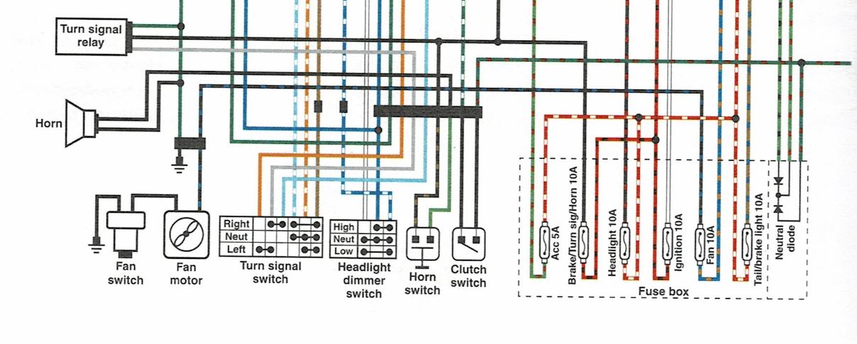 |
|
|
|
|
Logged
|
|
|
|
Skinhead
Member
Posts: 8742
J. A. B. O. A.
Troy, MI
|
|
« Reply #18 on: June 06, 2023, 03:02:17 PM » |
|
Well, I'm done here with the exception of this comment: All that should be needed is the power coming from the switch connected to 85 and any ground, could be the 2nd wire from the horn connected to 86. you said in reply 8 " In theory when I press the button this should complete circuit between 85 and 86 sending power to 87 correct?"
85 and 86 are connected through the coil, there is no need to complete a circuit between them. All that is needed is power (from the switch when it is closed) to one and a ground to the other. Verify you have power and ground. I'm sorry if my graphic offended you, but I was merely trying to demonstrate graphically what you described. It really isn't that complicated.
I have my own air horn installed on my bike, and it will not work with the engine idling, I believe this is due to low voltage when the alternator isn't charging. The Horns (the OEM and air horn) are both connected in parallel, both work off idle. Also I have the compressor for the air horns powered on a separate circuit and an air reservoir (tank) and a danmarc fuel solenoid that is energized by the horn switch. If you have the horn switch controlling the compressor, there may not be enough voltage to the compressor to run it. Good luck.
|
|
|
|
« Last Edit: June 06, 2023, 03:18:50 PM by Skinhead »
|
Logged
|
Troy, MI |
|
|
|
Mooskee
|
|
« Reply #19 on: June 06, 2023, 05:06:57 PM » |
|
So lets get a little clearer in that there are two wires that went to the original horn, One being a positive and the other being a ground. I have tried either wire that went to the original horn as a trigger on pin 85 and had the other wire run to pin 86 which is grounded to the bike along with the NEW air horn grounded as well. They were all sharing the same grounding point. Terminal 30 on my relay which is the power in to the relay for the NEW horn comes off a 30 amp thermal breaker that has been verified to work. and then I have a wire from pin 87 on relay to complete the power circuit for the horn.
My point is that NO MATTER which wire that ran to the original horn is used to trigger the relay or ground the switch does not activate the horn when pressed. I have verified the switch is good with a meter. LOL the only thing I have NOT tried is to take the two wires that used to run to the horn and run them to pin 85 and use pin 86 as a ground. I say this cause I know power is only present in the two wires that ran to the original horn when the button is pressed.
What you wrote above will work. The horn circuit is as you stated. Here is a better schematic of the bike wiring for the horn. 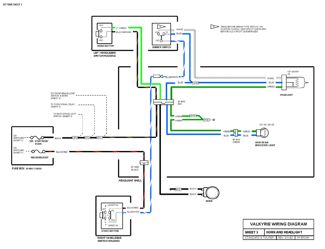 If you look at the drawing you will see that if you connected the two wires that were connected to the horn to 85 & 86 (ground and power) when you push the horn button you would turn on the relay. So with your 30 amp breaker wire connected to 30, and the horn + connected to 87, and the other side of the horn grounded, The horn button will blow the horn via the relay. Since you say it did not, one or more of the following is the problem. 1- The 10 AMP Stop/Turn / Horn fuse is blown. (Located under right hand side cover in small black box.) You can also just verify you have stop and turn lights. 2. Your 30 Amp thermal breaker is tripped or faulty. Hook your horn directly to that wire and ground, and see it it works. 3. There is a bad connection or bad component. You can check the relay with a 9V battery across 85 & 86. You should feel or hear it click unless it is solid state. If you cant figure it out, PM me and we will get on the phone and figure it out. Dave |
|
|
|
« Last Edit: June 06, 2023, 05:17:15 PM by Mooskee »
|
Logged
|
|
|
|
Dragunslayer
Member
Posts: 236
"AN APEX IS A TERRIBLE THING TO WASTE"
Robertsville, MO
|
|
« Reply #20 on: June 06, 2023, 06:54:15 PM » |
|
So lets get a little clearer in that there are two wires that went to the original horn, One being a positive and the other being a ground. I have tried either wire that went to the original horn as a trigger on pin 85 and had the other wire run to pin 86 which is grounded to the bike along with the NEW air horn grounded as well. They were all sharing the same grounding point. Terminal 30 on my relay which is the power in to the relay for the NEW horn comes off a 30 amp thermal breaker that has been verified to work. and then I have a wire from pin 87 on relay to complete the power circuit for the horn.
My point is that NO MATTER which wire that ran to the original horn is used to trigger the relay or ground the switch does not activate the horn when pressed. I have verified the switch is good with a meter. LOL the only thing I have NOT tried is to take the two wires that used to run to the horn and run them to pin 85 and use pin 86 as a ground. I say this cause I know power is only present in the two wires that ran to the original horn when the button is pressed.
What you wrote above will work. The horn circuit is as you stated. Here is a better schematic of the bike wiring for the horn. If you look at the drawing you will see that if you connected the two wires that were connected to the horn to 85 & 86 (ground and power) when you push the horn button you would turn on the relay. So with your 30 amp breaker wire connected to 30, and the horn + connected to 87, and the other side of the horn grounded, The horn button will blow the horn via the relay. Since you say it did not, one or more of the following is the problem. 1- The 10 AMP Stop/Turn / Horn fuse is blown. (Located under right hand side cover in small black box.) You can also just verify you have stop and turn lights. 2. Your 30 Amp thermal breaker is tripped or faulty. Hook your horn directly to that wire and ground, and see it it works. 3. There is a bad connection or bad component. You can check the relay with a 9V battery across 85 & 86. You should feel or hear it click unless it is solid state. If you cant figure it out, PM me and we will get on the phone and figure it out. Dave OMG I had it wired correctly on day one but due to some poor handling ( a few sparks were made on accident) I had blown the horn fuse in the fuse panel. After going over the wiring diagram it came to me that there has to be a fuse. I go down and check it and sure enough it is blown. Swap out for a good fuse and rewrite relay and HONK HONK 130 decibel air horn. Thanks for the help and the patience, it’s always the simple things that trip me up it seems. |
|
|
|
|
Logged
|
Kevin Reinhold AKA Dragunslayer
Robertsville, Mo
1999 Honda Valkyrie Tourer
2015 Kawasaki Concours 14
2016 Suzuki GSXS-1000F
"AN APEX IS A TERRIBLE THING TO WASTE"
|
|
|
Dragunslayer
Member
Posts: 236
"AN APEX IS A TERRIBLE THING TO WASTE"
Robertsville, MO
|
|
« Reply #21 on: June 06, 2023, 07:00:04 PM » |
|
Follow the wiring diagram so you understand how the original horn and switch are connected. There is only 1 wire going to the horn from the switch, that is the + wire that runs from the horn back through the horn switch and then to the fuse box, ignition switch and then the battery. The other wire going to the horn goes to ground. Take it bit by bit. First verify your getting 12V to the wires your going to connect to 85 & 86 when you depress the horn switch. Once you have that connect them to 85 & 86 terminals Then verify you have continuity between 30 & 87 when you depress the horn switch. Once you have continuity between 30 & 87 you can run your hot wire through that path to the new horn. Please see the I just made as the only issue with the way I had it wired was the fuse on the bike that I somehow blew along he way. But thanks for making me think a little harder. |
|
|
|
|
Logged
|
Kevin Reinhold AKA Dragunslayer
Robertsville, Mo
1999 Honda Valkyrie Tourer
2015 Kawasaki Concours 14
2016 Suzuki GSXS-1000F
"AN APEX IS A TERRIBLE THING TO WASTE"
|
|
|
Dragunslayer
Member
Posts: 236
"AN APEX IS A TERRIBLE THING TO WASTE"
Robertsville, MO
|
|
« Reply #22 on: June 06, 2023, 07:00:48 PM » |
|
Well, I'm done here with the exception of this comment: All that should be needed is the power coming from the switch connected to 85 and any ground, could be the 2nd wire from the horn connected to 86. you said in reply 8 " In theory when I press the button this should complete circuit between 85 and 86 sending power to 87 correct?"
85 and 86 are connected through the coil, there is no need to complete a circuit between them. All that is needed is power (from the switch when it is closed) to one and a ground to the other. Verify you have power and ground. I'm sorry if my graphic offended you, but I was merely trying to demonstrate graphically what you described. It really isn't that complicated.
I have my own air horn installed on my bike, and it will not work with the engine idling, I believe this is due to low voltage when the alternator isn't charging. The Horns (the OEM and air horn) are both connected in parallel, both work off idle. Also I have the compressor for the air horns powered on a separate circuit and an air reservoir (tank) and a danmarc fuel solenoid that is energized by the horn switch. If you have the horn switch controlling the compressor, there may not be enough voltage to the compressor to run it. Good luck.
Please see the I just made as the only issue with the way I had it wired was the fuse on the bike that I somehow blew along he way. But thanks for making me think a little harder. |
|
|
|
|
Logged
|
Kevin Reinhold AKA Dragunslayer
Robertsville, Mo
1999 Honda Valkyrie Tourer
2015 Kawasaki Concours 14
2016 Suzuki GSXS-1000F
"AN APEX IS A TERRIBLE THING TO WASTE"
|
|
|
|
Timbo1
|
|
« Reply #23 on: June 06, 2023, 07:37:30 PM » |
|
Please see the I just made as the only issue with the way I had it wired was the fuse on the bike that I somehow blew along he way. But thanks for making me think a little harder.
Glad you got it going. |
|
|
|
|
Logged
|
|
|
|
|
Mooskee
|
|
« Reply #24 on: June 06, 2023, 10:59:43 PM » |
|
Glad you got it working. You also gained some good experience. And maybe a few bad experiences.
Ride safely,
Dave
|
|
|
|
|
Logged
|
|
|
|
|
RonW
|
|
« Reply #25 on: June 07, 2023, 12:57:58 AM » |
|
Awesome! A 'honk if you like' post, lol. Some people advise disconnecting the battery when working on electricals. But who does that? They might have a point, though. If you blow the horn fuse you also won't have brake lights, turn signals, tail lights and front running lights as they share the same fuse (graphic, below). Thusly, the air horn should be powered directly from the battery's positive terminal isolating it from the stock horn circuit and fuse. The 86 trigger wire to the relay doesn't pose a hazard since the relay's 85/86 trigger circuit isn't electrically connected to the air horn's +12 power wire (87 pin).  |
|
|
|
« Last Edit: July 05, 2023, 03:02:31 PM by RonW »
|
Logged
|
2000 Valkyrie Tourer
|
|
|
|
RonW
|
|
« Reply #26 on: June 10, 2023, 08:29:28 PM » |
|
Dragunslayer, did you splice an inline fuse on the airhorn's +12 wire? Just asking.
|
|
|
|
|
Logged
|
2000 Valkyrie Tourer
|
|
|
|
Mooskee
|
|
« Reply #27 on: June 11, 2023, 11:37:00 AM » |
|
Dragunslayer, did you splice an inline fuse on the airhorn's +12 wire? Just asking.
He stated he had 30 of the relay going to a 30 amp thermal breaker and 87 of the relay going to the horn. So yes, the + of the horn would be fused. |
|
|
|
|
Logged
|
|
|
|
|
RonW
|
|
« Reply #28 on: June 11, 2023, 12:42:27 PM » |
|
*thermal breaker* yea that what's it was. Instead of *fuse,* thanks.
|
|
|
|
|
Logged
|
2000 Valkyrie Tourer
|
|
|
|
rug_burn
|
|
« Reply #29 on: June 30, 2023, 09:20:12 AM » |
|
Me? I would check where the problem is in the original setup as seen in the original simple schematic in Mooskee's post.
Test the relay with a lightbulb first, to make sure it's functioning right, then put it in your horn circuit. This also verifies all the wiring up to the relay is good.
Just temporarily disconnect the horn at 87, and solder a couple wires to any random 12v low watt bulb, such as a side marker bulb. Then run one from the relay terminal 87 and the other to ground, and it should light up when you hit the horn button.
Then once this works, you know the relay is good. What current is that relay good for? The horn might be too much for it, in which case, your relay would already be toast. But I doubt it since it's an automotive relay.
The little diode (electronic one-way valve) between 85 and 86 is good, but another slightly larger one would be good too, between the horn wires since a horn is a big old coil, producing a big old kickback when de-energized. The arrow part of the diode pointing away from the ground (-) side.
It's not totally clear in that schematic where the ground (-) side of the relay coil (#86) goes, but it should go to ground.
|
|
|
|
« Last Edit: June 30, 2023, 09:36:23 AM by rug_burn »
|
Logged
|
...insert hip saying here..
|
|
|
|


