I decided I wanted to add cruise to my Valkyrie. After doing a lot of research on the forum I came to the conclusion I wanted to use a CCS100 since it would work from a tachometer signal only and it does not require the install of a separate speed sensor. In researching I was only able to find only two places still selling it. It was not the Audiovox but a reproduction. One was
http://www.murphskits.com/catalog/product_info.php?products_id=422 and the other was on e-bay.
I used the following link as my guide for the install with my own changes.
http://www.valkyrieriders.com/shoptalk/cruise-control.htmI purchased the CCS100 with a vacuum canister from
http://www.murphskits.com It was not as cheap as they used to be from what I had seen in other posts.
It cost $197.00 for both.
I started by removing the gas tank and air box.

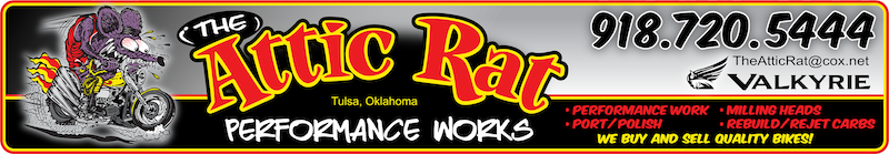
I decided I would Also de-smog the bike during the process. I found that some previous owner had already disable the pare valve by plugging the hose internally with a cap from a 90w bottle. I removed the pare valve and the two reed valves. I keep the 6 chrome pipes and just put vacuum caps over the ends of each pipe. I like the way the chrome pipes look. I also had to plug one of the connections on the bottom of the air box now that the pare valve is removed. I highlighted what I removed in the photo.

I started to fabricate the bracket to hold the control unit. Started using some cardboard to cut a template.

I used some square tubing I had around the shop for the metal.

I mounted it under the left mirror.

Painted it black with rustolium bed liner.


I used shrink wrap to cover all the wires from the control unit.

I mounted the vacuum control unit under the seat in the tool box area. I had to cut/grind some of the plastic out to make it fit. There is no longer any room for any tools. I ran the cable and vacuum hose out of the left of the tool box and the wires out of the right of the toolbox through hols I drilled.


I routed my cable differently then they did in the guide I was following. I wanted to keep the cable were it could not be seen from the outside of the bike.
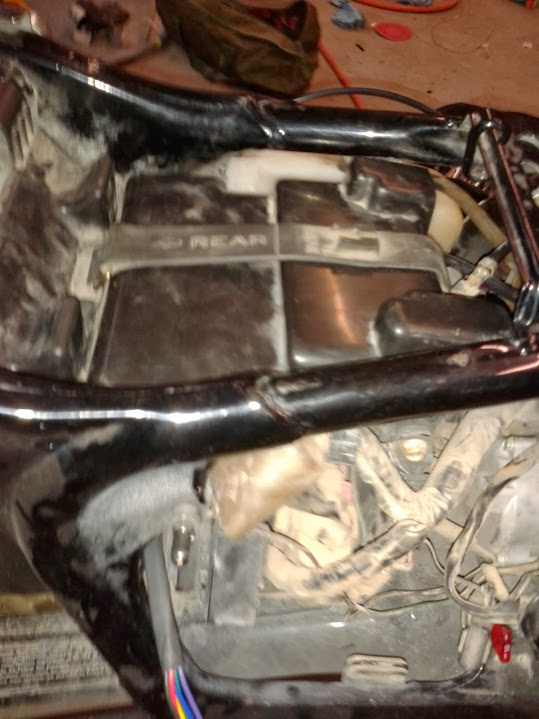
This is the start of the bracket fabrication. I used the same square tubing to make the bracket. I welded two peaces together to make it more ridged. I mounted it using one of the bolts that was removed when I de-smoged. I used a spacer under the bracket that I had left over from when I had the turbo out of my ford Excursion. The turbo install kit comes with new spacers.
With the cable mounted to the bracket

I connected the cable to the fuel control on the left side between the two aft carburetors. Removed cotter pin installed cable and reinstalled cotter pin.

pic of it all connected

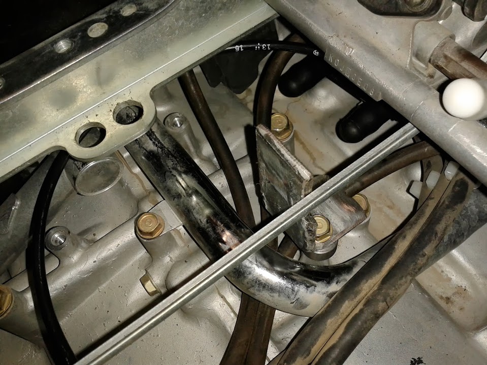
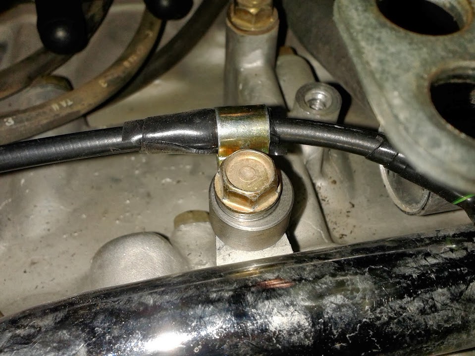
Added a cable clamp with another one of the turbo spacers. I removed the bolt that was there and replaced it with one of the longer ones I removed when I de-smoged earlier.
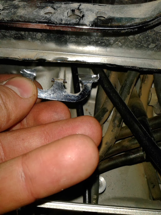
I needed to make room for the vacuum canister. I had to cut this piece off the aft rail that connect the left and right banks of carburetors. It had to hoses going through it that came from the carburetor banks. I moved the hoses to the front rail.
Here is what it looks like with the vacuum canister installed. All the highlighted stuff I added.
I also had to add vacuum lines from the five intake manifolds to the canister. The sixth on is already used for the fuel petcock. The canister had a built in check valve to I did not have to put separate check valves inline.

After reinstalling the fuel line

I connected the wires as suggested in the other post I used as my guide.


Put it all back together and took it out for a test drive and it work perfect the first time.
Hope my pics might help some one else with the same mode.