In the cases above - the trade off is more on the reception of the FM signals - since these types of setups are tuned obviously for transmission, at whatever frequency range of the transmitting radio. Tuning the antenna for reception of the FM signal will then not be "optimum" but by most anyone's standards, acceptable. ( I base this on knowing that a short antenna properly loaded will not receive as strongly, longer waves as a longer antenna would. And conversely, the same holds true for long antennas and short wavelengths. Electrically spoofing the circuit through the use of capacitors doesn't make up for the initial property of the radiator / receptor relationship. ) Remember when the Optimum FM antenna for a vehicle was a 54" whip?!
Let's examine the use of a matching circuit and look at the relationships of wavelength vs physical length WRT a CB antenna and the FM broadcast band frequencies.
A 1/4w vertical at 100MHz is ~2.5ft in length. The stock "center-loaded" Hondaline CB antenna (or any other 'resonant' 1/4w CB whip) is physically longer than this, and
electrically appears around 9ft in length. Such an arrangement also appears to be
inductive at 100MHz, the center of the FM broadcast band.
How do we match an inductive load? Simple - with a series capacitor arrangement: ANT -----------[\(---------- FM RADIO
Those who wish a more thorough explanation of what is going on with an antenna, radio and coupling circuits may wish to peruse the following:
http://en.wikipedia.org/wiki/Impedance_matchingThe above being stated, if an antenna is significantly
shorter than its intended frequency of operation (and we're talking many wavelengths here, BTW) then capture area and radiator area will be minimized and will affect the overall efficiency of the system. An electrically "longer" antenna - when matched properly to a load or generator impedance - will actually exhibit some free-space gain over an equivalent "resonant" antenna.
This fact is not lost on CB and amateur antenna manufacturers; many of their vertical (ground plane) antenna products are constructed as 5/8w or series-phased, multiple 5/8w radiators. Each of these sections is electrically longer than an 'optimum' 1/2w dipole and is matched to the transmitter through the use of (you guessed it) a series capacitor.
Let's be honest here for a moment..... How many of us still listen to more than a little on the FM radio? I find with satellite and my trusty Ipod/Zune/whatever file player you have - My time on the FM dial grows ever increasingly less.
Let's be honest here for one more moment..... How many of us would choose to operate a CB as opposed to the FM bands more available now than ever if our radios had that option?! Can you imagine the truckers on "family band"?
Here's another tidbit:
Automotive stereo-equipment manufacturers have long realized that their products would be fed via so-called "compromise" antennas, and as such have designed their receiver front ends with a good amount more gain than the average home-entertainment system has.
They'll work effectively with the figurative "wet noodle" connected to them.
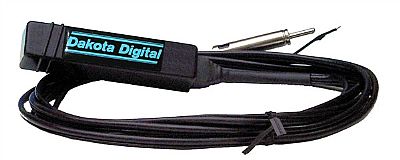
One of my I/Ses has the following antenna installed inside the fairing and mounted to the right-hand stay. In spite of the very limited capture area of the setup, its FM stereo works surprisingly well when fed with the Dakota.


