|
turtle254
|
 |
« Reply #40 on: December 06, 2018, 10:41:26 AM » |
|
End play is trans shaft moving in and out of trans, not side to side movement; which might or not be a problem. Lots of designs out their running with end play limited with no known problems, so I think this is a reach.
When i was referring to end play I was talking about the gear shift arm, not the splined shaft that it attaches to. It would seem to me that when you bolt the modification together and tighten it down making sure that the gear shift arm is in the center of end play, it does not matter which side the support is on. Avanti was talking about end play on "trans bearing", so I decided to not load the in and out movement of trans shaft by leaving more clearance on the bearing length at frame bolt bracket . Loading a bearing race by bringing end play to "0" can comprise to bearing design, it needs to float and not have pressure in and out on the race. Looks like Avanti has delete his comments, hope he comes back because he was right. The shift spindle sits in needle bearings, not a conventional bearing with balls and races. It's axial motion is limited only by the fork-shaped part pressed or welded onto it, and by the back end of it pressing against the gearshift arm A. If you apply axial pressure to the end of the spindle, it will rub more on arm A, but no damage can occur to the needle bearings. It would take a lot of pressure on the spindle to create a significant amount of wear on arm A because of the limited range of motion of either; I think this much axial force would be felt in harder shifting. This is from the photos on pages 10.7 and 10.8 of the FSM. The radial forces that these mods seek to reduce, however, will slowly damage the bearing surfaces, while causing stress to the seal. I think for safety I'll stick with " leaving more clearance on the bearing length at frame bolt bkt " and let the trans spindle float. |
|
|
|
|
 Logged
|
|
|
|
|
indybobm
|
|
« Reply #41 on: December 06, 2018, 11:26:22 AM » |
|
Not sure what the difference of opinion is on this. Is there a difference of opinion?
|
|
|
|
|
Logged
|
So many roads, so little time
VRCC # 5258
|
|
|
|
RonW
|
|
« Reply #42 on: December 07, 2018, 02:02:42 AM » |
|
The shift spindle sits in needle bearings, not a conventional bearing with balls and races. It's axial motion is limited only by the fork-shaped part pressed or welded onto it, and by the back end of it pressing against the gearshift arm A. If you apply axial pressure to the end of the spindle, it will rub more on arm A, but no damage can occur to the needle bearings. It would take a lot of pressure on the spindle to create a significant amount of wear on arm A because of the limited range of motion of either; I think this much axial force would be felt in harder shifting. This is from the photos on pages 10.7 and 10.8 of the FSM. The radial forces that these mods seek to reduce, however, will slowly damage the bearing surfaces, while causing stress to the seal.
The oil seal is already stressed due to the slop on the stock design, so no harm there. My opinion is that as long as you leave some slop in whatever mod is used, you'll eliminate enough stress on the needle bearing, or at least have a trade off that's still an improvement. The simplest place for a designed clearance is at the pivot. Specifically the pivot point where the support bracket is pinned or bolted to the anchor bracket. By support bracket, I mean the metal piece that gets attached to the shifter arm's rod at it's outboard end (bottom pic). Then an anchor bracket secures the support bracket to the engine guard bolt. It's almost impossible to perfectly align the hole in the support bracket dead center with the gearshift spindle so their swings match each other's. Analogous to a vehicle's two front wheels aligned with each other. (Bottom pic, exaggerated.) The misalignment would rotate the gearshift spindle unevenly on the spindle's needle bearing. As you already noted, the gearshift spindle isn't secured on it's inner end, so the exterior shifter arm can pry the spindle sideways on it's single needle bearing. More over the spindle doesn't spin 360° in the needle bearing. The spindle moves like a pendulum back and forth perhaps wearing out the same quadrant on the needle bearing. Therein lies the rub so on. Anyways if some clearance aka slop is designed on purpose on a given mod's geometry, the resultant slop would allow the movable parts to self-adjust for any misalignment. True, as the pivot point wears, clearance is created and you end up with the same thing but it's more ideal to design a clearance there from the get go. 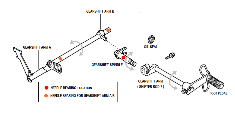 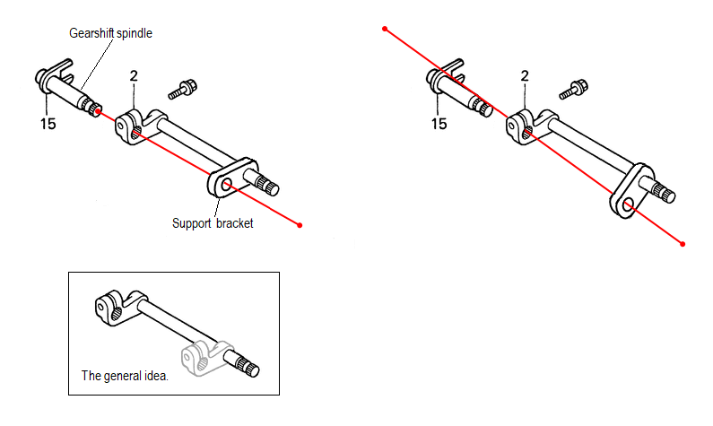 |
|
|
|
« Last Edit: December 07, 2018, 09:30:28 AM by RonW »
|
Logged
|
2000 Valkyrie Tourer
|
|
|
|
pancho
|
|
« Reply #43 on: December 07, 2018, 03:27:39 AM » |
|
You got it,,, creates and supports the ideal of what was there before the mod, and it is easy to get the pivot position right as you have the assembly of the gear shift arm to measure and go by.
As I stated earlier, if you wanted to make multiple copies of these, you would have to make a jig that was precise to insure alignment, but for a one off, it can be done with simple tools as I did.
It's almost impossible to perfectly align the hole in the support bracket dead center with the gearshift spindle so their swings match each other's.
Not sure I agree with that statement RonW, as you have the gearshift arm to go by, you just reproduce what is already there. You can get as close as your measuring and cutting tools will allow. (not saying I got it PERFECT in my prototype, but close enough) To me, as long as you are in the ballpark and causing no binding, it has to be an improvement....?? Look at the amount of lateral play there is to work within.
|
|
|
|
« Last Edit: December 07, 2018, 04:22:08 AM by pancho »
|
Logged
|
The most expensive things you will purchase, are those things you would not have needed if you had listened and obeyed.
|
|
|
|
pancho
|
|
« Reply #44 on: December 07, 2018, 05:02:43 AM » |
|
While it never entered my mind before (never considered making a bad one), you guys digging into this made me think about it and realize that if one of these was made that was substantially out of alignment, it could cause problems with the bearing and shaft in the long run. I may have oversimplified this as I trust my skills.
Proceed with this modification in accordance with your confidence that the pivot point can be precisely aligned with the gearshift spindle. This is true to any modification of this type including the original.
|
|
|
|
|
Logged
|
The most expensive things you will purchase, are those things you would not have needed if you had listened and obeyed.
|
|
|
|
The emperor has no clothes
|
|
« Reply #45 on: December 07, 2018, 05:21:05 AM » |
|
While it never entered my mind before (never considered making a bad one), you guys digging into this made me think about it and realize that if one of these was made that was substantially out of alignment, it could cause problems with the bearing and shaft in the long run. I may have oversimplified this as I trust my skills.
Proceed with this modification in accordance with your confidence that the pivot point can be precisely aligned with the gearshift spindle. This is true to any modification of this type including the original.
I think it is a nice simple mod. I plan doing it myself. I think as long as the distances are the same and everything is aligned correctly there will be no issues whatsoever. Thanks for thinking this mod thru.  |
|
|
|
|
Logged
|
|
|
|
MarkT
Member

Posts: 5197
VRCC #437 "Form follows Function"
Colorado Front Range - elevation 2.005 km

|
|
« Reply #46 on: December 07, 2018, 06:47:00 AM » |
|
I did 2 different versions of Ammpro's mod on my 2 daily riders and both shift noticably better. I think most any carefully applied version of the mod is better than before you do it.
|
|
|
|
|
Logged
|
|
|
|
|
pancho
|
|
« Reply #47 on: December 07, 2018, 07:20:30 AM » |
|
Avanti, if you are still following this topic, I want to apologize to you. While I did want you to correct your rendering (thanks for taking the time), as it was like fake news and able to cause misleading thinking, I could have been more diplomatic, or PMed you about it. Truly sorry and hope you forgive me.
|
|
|
|
|
Logged
|
The most expensive things you will purchase, are those things you would not have needed if you had listened and obeyed.
|
|
|
|
WintrSol
|
|
« Reply #48 on: December 07, 2018, 07:50:33 AM » |
|
I measured the radial end play of my gearshift arm in the vertical direction, and got about 1/16", which must all be due to the fit of the needle bearing. I would guess that I could move the end of that arm in a circle of about that diameter, depending on the wear pattern of the bearing, but perhaps it's an oval, and that is the major diameter. In any case, I'd guess that if there is enough range for adjustment so you can hold the end of the gearshift arm within that circle or oval, no additional pressure would be applied to the needle bearing, and it should be significantly less during shifting.
|
|
|
|
|
Logged
|
98 Honda Valkyrie GL1500CT Tourer
Photo of my FIL Jack, in honor of his WWII service
|
|
|
|
RonW
|
|
« Reply #49 on: December 07, 2018, 10:39:15 AM » |
|
Quick question ..... is the gearshift spindle free to move in and out a few mm's? perpendicular to the length of the bike. Perhaps this was discussed already. 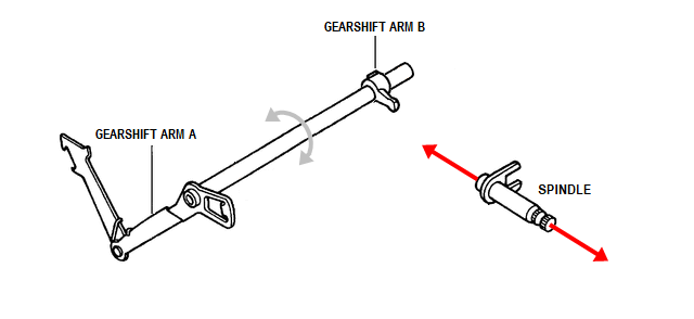 |
|
|
|
|
Logged
|
2000 Valkyrie Tourer
|
|
|
|
turtle254
|
|
« Reply #50 on: December 07, 2018, 11:16:47 AM » |
|
Yes … with out Mod.
|
|
|
|
|
Logged
|
|
|
|
|
indybobm
|
|
« Reply #51 on: December 07, 2018, 11:17:14 AM » |
|
Once the gear shift arm is bolted to the spindle, moving the gear shift arm in and out is the same as moving the spindle. I think that if you assemble the brace for the pivot so the the gear shift arm is in the center if its left/right movement it would be good.
|
|
|
|
|
Logged
|
So many roads, so little time
VRCC # 5258
|
|
|
|
pancho
|
|
« Reply #52 on: December 07, 2018, 05:53:43 PM » |
|
Quick question ..... is the gearshift spindle free to move in and out a few mm's? perpendicular to the length of the bike. Perhaps this was discussed already. It has come up already RonW,, the axial end play is the same with the mod as it was before. If you study the picture shot from underneath with the mod installed, you can see the clearance that provides for this. |
|
|
|
|
Logged
|
The most expensive things you will purchase, are those things you would not have needed if you had listened and obeyed.
|
|
|
|
Avanti
|
|
« Reply #53 on: December 07, 2018, 10:14:54 PM » |
|
Avanti, if you are still following this topic, I want to apologize to you. While I did want you to correct your rendering (thanks for taking the time), as it was like fake news and able to cause misleading thinking, I could have been more diplomatic, or PMed you about it. Truly sorry and hope you forgive me.
Thank you for your apology; I do forgive you. Yes, I am still following this topic; I believe it is a good design and a modification worth the effort. |
|
|
|
|
Logged
|
|
|
|
Jersey
Member
Posts: 545
VRCC #37540
Southern Maryland
|
|
« Reply #54 on: December 08, 2018, 04:29:01 AM » |
|
Nice drawing. (What software?) I'm wondering if you could change the placement of the Support Bracket piece in the drawing? (In the General Idea box.) Rotate it 180 degrees so the clamping section is on the extension and the plain hole is free for the mounting to the brace. While the manufacturing of the support bracket would take a little, I think it could grip enough to work for this purpose. Don't need the involute spline on the support piece. Also, could add an Allen Set Screw on the perpendicular side for extra 'bite'. That design could then be installed without any welding. Just a thought. |
|
|
|
|
Logged
|
Jersey
|
|
|
|
Avanti
|
|
« Reply #55 on: December 08, 2018, 08:00:34 AM » |
|
This is what i did. Bracket or brace is on the other side to allow room for the thickness of the clamping surface on the shift arm and the radial spherical bearing at the other end. The pin goes through a bushing in the lower end of the brace so it can float and press into the radial spherical bearing which allows for alignment. This was the best steady state I could come up with; working in the parameters that are already set and the ones I felt would give the best result. Ignore as needed.  |
|
|
|
« Last Edit: December 09, 2018, 07:30:03 PM by Avanti »
|
Logged
|
|
|
|
|
turtle254
|
|
« Reply #56 on: December 08, 2018, 08:21:48 AM » |
|
For what its worth, I used two hang down brackets to sandwich the bearing bracket(brk attached to shift arm) between them for a solid support and a gap for axis play.
|
|
|
|
|
Logged
|
|
|
|
Jersey
Member
Posts: 545
VRCC #37540
Southern Maryland
|
|
« Reply #57 on: December 08, 2018, 08:27:15 AM » |
|
For what its worth, I used two hang down brackets to sandwich the bearing bracket(brk attached to shift arm) between them for a solid support and a gap for axis play.
Nice design, but can you expand on the 'hang down bracket'? does it provide enough bit into the shaft lever to hold position? |
|
|
|
|
Logged
|
Jersey
|
|
|
|
turtle254
|
|
« Reply #58 on: December 08, 2018, 08:49:21 AM » |
|
For what its worth, I used two hang down brackets to sandwich the bearing bracket(brk attached to shift arm) between them for a solid support and a gap for axis play.
Nice design, but can you expand on the 'hang down bracket'? does it provide enough bit into the shaft lever to hold position? Other way around, the double brackets with washer between one end and shift arm bracket(pivot point) other end are the ones that hangs down from frame bolt. |
|
|
|
|
Logged
|
|
|
|
|
RonW
|
|
« Reply #59 on: December 09, 2018, 03:18:02 AM » |
|
Nice drawing. (What software?) I'm wondering if you could change the placement of the Support Bracket piece in the drawing? (In the General Idea box.) Rotate it 180 degrees so the clamping section is on the extension and the plain hole is free for the mounting to the brace. Just Paint (MS) standard issue on Window computers. As it's a 2 dimensional isometric drawing, the individual parts can't be rotated.
While the manufacturing of the support bracket would take a little, I think it could grip enough to work for this purpose. Don't need the involute spline on the support piece. Also, could add an Allen Set Screw on the perpendicular side for extra 'bite'. That design could then be installed without any welding. Just a thought.
Agreed, if welding isn't an option, then allen screws are about the only way to secure the support bracket to the shifter rod but that's only if the support bracket is thick enough. Well, maybe collars on both sides of a thinner support bracket pegged horizontally ?? |
|
|
|
|
Logged
|
2000 Valkyrie Tourer
|
|
|
Jersey
Member
Posts: 545
VRCC #37540
Southern Maryland
|
|
« Reply #60 on: December 09, 2018, 09:12:28 AM » |
|
Probably too expensive to make, but this might work.  |
|
|
|
|
Logged
|
Jersey
|
|
|
|
Avanti
|
|
« Reply #61 on: December 09, 2018, 12:41:10 PM » |
|
Reminds me of going Darkside, so many options.
|
|
|
|
« Last Edit: December 09, 2018, 07:30:39 PM by Avanti »
|
Logged
|
|
|
|
Tfrank59
Member
Posts: 1364
'98 Tourer
Western Washington
|
|
« Reply #62 on: December 09, 2018, 12:55:50 PM » |
|
Yes and it's a double row needle bearing because the Honda engineers realized how much side load that dog leg shifter would create. That's why for many this fix isn't necessary but there are exceptions and I guess I'm one.
|
|
|
|
|
Logged
|
-Tom
Keep the rubber side down. USMC '78-'84
'98 Valkyrie, ‘02 VTX 1800, '96 Royal Star, '06 Drifter, '09 Bonneville, '10 KTM 530, '04 XR 650, '76 Bultaco, '81 CR 450, '78 GS 750...
|
|
|
|
RonW
|
|
« Reply #63 on: December 10, 2018, 02:33:47 AM » |
|
Probably too expensive to make, but this might work. Excellent! For the key, since it's impossible to machine a keyway slot on the shifter rod, a peg might work, to keep the support bracket from rotating. Or, you could start off with a T-shaped sheet of metal and round off the peg part of the T (inset graphic). Don't have to get the fit super tight since the peg is captured. It ain't going anywhere.  |
|
|
|
|
Logged
|
2000 Valkyrie Tourer
|
|
|
|
pancho
|
|
« Reply #64 on: December 10, 2018, 08:50:27 AM » |
|
Hey guys, am I missing something or are all these elaborate mechanisms just to get around a weld?? Mama Honda used a weld on the other end, good enough for them.... I understand that not everyone welds, but it isn't an obscure skill,, there are many people in even the smallest towns that weld.. I think I'm missing something or you guys are just having fun designing stuff.... I understand!
|
|
|
|
|
Logged
|
The most expensive things you will purchase, are those things you would not have needed if you had listened and obeyed.
|
|
|
|
Pete
|
|
« Reply #65 on: December 10, 2018, 09:02:03 AM » |
|
Yes Pancho I believe that is the case. As many do not have access to a welder and do not realize how easy and cheap the new wire welders are to buy and use.
For years I was the same way, but since acquiring a wire welder I have seen the light. Anyone who works on anything metallic needs a wire welder. No question in my mind.
|
|
|
|
|
Logged
|
|
|
|
Jersey
Member
Posts: 545
VRCC #37540
Southern Maryland
|
|
« Reply #66 on: December 10, 2018, 09:54:10 AM » |
|
Hey guys, am I missing something or are all these elaborate mechanisms just to get around a weld?? Mama Honda used a weld on the other end, good enough for them.... I understand that not everyone welds, but it isn't an obscure skill,, there are many people in even the smallest towns that weld.. I think I'm missing something or you guys are just having fun designing stuff.... I understand!
I weld, but also enjoy designing. For me it was an exercise in expanding on your design to create something that anyone could bolt on. Plus it fun exchanging ideas with others! |
|
|
|
|
Logged
|
Jersey
|
|
|
Jersey
Member
Posts: 545
VRCC #37540
Southern Maryland
|
|
« Reply #67 on: December 10, 2018, 10:05:15 AM » |
|
Probably too expensive to make, but this might work. Excellent! For the key, since it's impossible to machine a keyway slot on the shifter rod, a peg might work, to keep the support bracket from rotating. Or, you could start off with a T-shaped sheet of metal and round off the peg part of the T (inset graphic). Don't have to get the fit super tight since the peg is captured. It ain't going anywhere. The slot in the clamp wasn't for a Key, but just for compression movement of the clamp. Based on my sketchy engineering calculations, it appears this type of clamp design will sufficiently handle over 50 lbs of pressure on the foot lever before slipping. I measured gear shifting to need around 25 lbs of force. |
|
|
|
« Last Edit: December 10, 2018, 10:46:59 AM by Jersey »
|
Logged
|
Jersey
|
|
|
|
turtle254
|
|
« Reply #68 on: December 10, 2018, 11:10:43 AM » |
|
 https://imgur.com/a/W5ctAmg https://imgur.com/a/W5ctAmgMy simplest design ... could not get pic to show in quote, just have to click on imgur site. |
|
|
|
« Last Edit: December 10, 2018, 11:32:58 AM by turtle254 »
|
Logged
|
|
|
|
|
Avanti
|
|
« Reply #69 on: December 10, 2018, 11:23:23 AM » |
|
Probably too expensive to make, but this might work. Excellent! For the key, since it's impossible to machine a keyway slot on the shifter rod, a peg might work, to keep the support bracket from rotating. Or, you could start off with a T-shaped sheet of metal and round off the peg part of the T (inset graphic). Don't have to get the fit super tight since the peg is captured. It ain't going anywhere. The slot in the clamp wasn't for a Key, but just for compression movement of the clamp. Based on my sketchy engineering calculations, it appears this type of clamp design will sufficiently handle over 50 lbs of pressure on the foot lever before slipping. I measured gear shifting to need around 25 lbs of force. That is the type of clamping I used. If you look at the front forks, they are held in place in the triple tree with this type of clamping. |
|
|
|
|
Logged
|
|
|
|
|
RonW
|
|
« Reply #70 on: December 11, 2018, 05:58:27 AM » |
|
The slot in the clamp wasn't for a Key, but just for compression movement of the clamp.
Based on my sketchy engineering calculations, it appears this type of clamp design will sufficiently handle over 50 lbs of pressure on the foot lever before slipping. I measured gear shifting to need around 25 lbs of force.
your design is large enough to screw in a bolt if you like , on the cube part. 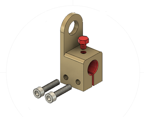 |
|
|
|
|
Logged
|
2000 Valkyrie Tourer
|
|
|
|
RonW
|
|
« Reply #71 on: December 11, 2018, 07:17:12 AM » |
|
Hey guys, am I missing something or are all these elaborate mechanisms just to get around a weld??
Affirmative! seems getting that *support bracket* onto the shifter rod is holding things up, maybe years. Not everybody haz wielding equipment. Then way easier to support the shifter rod out board the pedal. Meanwhile, below, the preferred embodiment of the present invention, well your version ®. Support bracket is in candy apple red. If you do get a wire welder get the 220 volt. Of course, if you have a reachable 220 volt outlet. Not sure if a stick welder is better. I have a Lincoln mig stored under my computer desk. 120 volts. Apt living don't give you much room for sure. Rear tire on the lanai (balcony). Locker room downstairs is filled to the gills. My xmas lights are packed in there some where. A few years ago gave up digging for them and bought new string lights.  |
|
|
|
« Last Edit: December 11, 2018, 07:25:22 AM by RonW »
|
Logged
|
2000 Valkyrie Tourer
|
|
|
|
WintrSol
|
|
« Reply #72 on: December 11, 2018, 07:34:52 AM » |
|
I kind of like Jersey's clamp idea, as it is not only reversible, but allows for careful alignment with the shift spindle. A welded bracket would require a lot of skill, or a jig to hold it in place, for the welder can keep that alignment true.
|
|
|
|
|
Logged
|
98 Honda Valkyrie GL1500CT Tourer
Photo of my FIL Jack, in honor of his WWII service
|
|
|
|
turtle254
|
|
« Reply #73 on: December 11, 2018, 08:50:53 AM » |
|
Did anyone open my pic … the bracket off bolt clamp on the shift petal is the easy way and no welding and reversible too. https://imgur.com/a/W5ctAmg the sandwich of the hang down bracket off frame bolt gives a solid support. The bolt thru to spline is head of bolt turned down to a press fit in recess. |
|
|
|
« Last Edit: December 11, 2018, 08:55:17 AM by turtle254 »
|
Logged
|
|
|
|
|
The emperor has no clothes
|
|
« Reply #74 on: December 11, 2018, 09:44:28 AM » |
|
Did anyone open my pic … the bracket off bolt clamp on the shift petal is the easy way and no welding and reversible too. https://imgur.com/a/W5ctAmg the sandwich of the hang down bracket off frame bolt gives a solid support. The bolt thru to spline is head of bolt turned down to a press fit in recess. Yes, I looked. It seemed identical to Ammpro's mod to me. |
|
|
|
|
Logged
|
|
|
|
|
turtle254
|
|
« Reply #75 on: December 11, 2018, 09:48:53 AM » |
|
Did anyone open my pic … the bracket off bolt clamp on the shift petal is the easy way and no welding and reversible too. https://imgur.com/a/W5ctAmg the sandwich of the hang down bracket off frame bolt gives a solid support. The bolt thru to spline is head of bolt turned down to a press fit in recess. Also petal can be move to any place. The sandwich makes a extremely strong and no Twist on bearing. Yes, I looked. It seemed identical to Ammpro's mod to me. Mostly, except drilling the shift petal and solid support with bolt going all the way in the recess and the sandwich of hang down bracket |
|
|
|
« Last Edit: December 11, 2018, 10:00:48 AM by turtle254 »
|
Logged
|
|
|
|
|
The emperor has no clothes
|
|
« Reply #76 on: December 11, 2018, 09:55:13 AM » |
|
I kind of like Jersey's clamp idea, as it is not only reversible, but allows for careful alignment with the shift spindle. A welded bracket would require a lot of skill, or a jig to hold it in place, for the welder can keep that alignment true.
I haven't done the mod yet. But it doesn't seem like it would be that hard to get it lined up accurately for welding. I thought I would use a long bolt or rod to hold it in alignment for the weld. |
|
|
|
|
Logged
|
|
|
|
|
turtle254
|
|
« Reply #77 on: December 11, 2018, 10:01:54 AM » |
|
Also petal can be move to any place. The sandwich makes a extremely strong and no Twist on bearing.
|
|
|
|
|
Logged
|
|
|
|
Tfrank59
Member
Posts: 1364
'98 Tourer
Western Washington
|
|
« Reply #78 on: December 11, 2018, 11:02:26 AM » |
|
Hey guys, am I missing something or are all these elaborate mechanisms just to get around a weld?? Mama Honda used a weld on the other end, good enough for them.... I understand that not everyone welds, but it isn't an obscure skill,, there are many people in even the smallest towns that weld.. I think I'm missing something or you guys are just having fun designing stuff.... I understand!
For a machinist, getting around using a weld is all the fun  |
|
|
|
|
Logged
|
-Tom
Keep the rubber side down. USMC '78-'84
'98 Valkyrie, ‘02 VTX 1800, '96 Royal Star, '06 Drifter, '09 Bonneville, '10 KTM 530, '04 XR 650, '76 Bultaco, '81 CR 450, '78 GS 750...
|
|
|
|
The emperor has no clothes
|
|
« Reply #79 on: December 11, 2018, 01:03:17 PM » |
|
Hey guys, am I missing something or are all these elaborate mechanisms just to get around a weld?? Mama Honda used a weld on the other end, good enough for them.... I understand that not everyone welds, but it isn't an obscure skill,, there are many people in even the smallest towns that weld.. I think I'm missing something or you guys are just having fun designing stuff.... I understand!
For a machinist, getting around using a weld is all the fun for a shade tree mechanic, a MIG welder is invaluable  |
|
|
|
|
Logged
|
|
|
|
|