|
jimtblood
|
 |
« on: January 13, 2019, 10:49:02 AM » |
|
i know this has been asked umpteen times but i have been reading and searching the board for information on converting my 2000 Valk to LED.
i understand i can get an LED flasher, stick LED bulbs in and do the diode mod.
what i would really like to do is switch to smoked clear lenses, have running/brake/turn on the rear and LED on the front and replace the brake light with an LED that is super bright.
are smoked clear lenses available and what parts should i use to accomplish what i want to do?
thanks in advance
jim
|
|
|
|
|
 Logged
|
|
|
|
MarkT
Member

Posts: 5196
VRCC #437 "Form follows Function"
Colorado Front Range - elevation 2.005 km

|
|
« Reply #1 on: January 13, 2019, 01:03:27 PM » |
|
I did exactly as you describe on Deerslayer and Jade. The clear lenses (and smoked) are available online. Here's a smoked tailight lens: https://www.amazon.com/Smoked-Taillight-Brake-DELUXE-VALKYRIE/dp/B072ZZ68HR?psc=1&SubscriptionId=AKIAILSHYYTFIVPWUY6Q&tag=duckduckgo-d-20&linkCode=xm2&camp=2025&creative=165953&creativeASIN=B072ZZ68HRRear screw lenses: https://www.amazon.com/Topzone-Motorcycle-Indicators-1997-2000-Valkyrie/dp/B071ZYWKBC?SubscriptionId=AKIAILSHYYTFIVPWUY6Q&tag=duckduckgo-d-20&linkCode=xm2&camp=2025&creative=165953&creativeASIN=B071ZYWKBCBottom screw lenses: https://www.amazon.com/Motorcycle-Indicators-1997-2000-Cruisers-Valkyrie/dp/B073VDVXYP?SubscriptionId=AKIAILSHYYTFIVPWUY6Q&tag=duckduckgo-d-20&linkCode=xm2&camp=2025&creative=165953&creativeASIN=B073VDVXYPLook to whether you need bottom screw or face screws. I installed a Radiantz LED board in the OEM tailight (which is WAY brighter than tungsten - did this same mod on our Magna too) and replaced the lens with a smoked one. The Radiantz array is expensive - $100 - but there's nothing else like it; they have no competition. It has 128 LEDs and they are REALLY bright. Here it is - doesn't include the fixture: https://www.radiantz.com/VTX-Shadow-Valkyrie-Aero-Sabre-Ace-Retro-p/9012-11.htm I did Run-Brake-Turn mods on the rear markers and installed red LED array bulbs. I seem to recall finding them at Autozone - the ones with 48 bulbs IIRC. Or these may be correct over at Radiantz: https://www.radiantz.com/Honda-VTX-LED-turn-signal-p/229.htm You need to check diameter of your fixtures, might need to be bottom screw lenses for these to work. I recall doing some mild mod/fab work to fit the arrays. I've bought a lot of LEDs at superbrightleds.com but they don't list the ones you need for this. I also found that the new surface-mount bulbs - the ones with yellow elements - are too sensitive to voltage. Wire 2 in parallel and one will always be way brighter than the other, apparently from slight differences in ground impedence. Get the old-school LED arrays with individual LEDs that look like miniature light bulbs - they don't have that problem. Here's an interesting point on logic and error modes. You want your rear lights really bright and visible. But not so much your front turns. In front - what if you're signalling a turn in error but you're not turning and it's a bright signal and traffic sees it - they may turn in front of your path. What if it's the same error but the light is more dim or it's washed out by your forward spots - they don't see it so they don't turn into your path (in theory - or at least as far as the signal is concerned). What if you are turning but you don't signal or they don't see the signal because it's not bright enough - no harm, they wait for you to pass but you don't as you're about to turn so they might be pissed but they wait, don't turn into your path. In back, you for sure want following traffic to see you're stopped or slowing for a left turn so it needs to be bright - same for the brake lights. If you leave it on in error - they may think you're inept but they won't run you over as you're not stopping. So my brake lights and rear turns are really bright. But the front turns - much less bright. This mod can be done using either 1156 sockets (single filiment - which is OEM) or you can replace them with 1157's (dual filiment). Easiest, if you do the latter, to just replace the pods with front pods. I designed the circuit for the Run Brake Turn mod which uses 2 std 5-pin relays with #87 & 87A pins (and a cpl diodes and resistors if you use 1156 sockets). I also installed smoked lenses in front & LED arrays, and did the indicator light mod. I improved that by using 2 red LED's inside the indicator instead of just isolating the grounds. See my writeup for run-brake-turn at http://www.horseapple.com/Valkyrie/Tech_Tips/VTX_signals/vtx_signals.html BTW the run-brake-turn mod also provides the correct signals if you want to rig the bike for trailers - with a std flat-4 plug & harness. Incidentally using std 5-pin relays and my circuit is cheaper than one of those ready-made kits, and the relays are available at any auto parts store if they ever need replacing. Mine haven't in years of use. But I have seen even good relays fail though it's pretty rare - good these relays are available everywhere just in case. Disadvantage, install requires soldering ability, is a little more work than a plug n play kit. However replacing the relays requires only a needlenose pliar - or your fingers if you're not ham-fisted like me. The tech page at the above link is more wordy than it needs to be. And I've departed from it substantially on the 2nd bike I did this mod on - Jade. That page was written when I did it 15 + years ago the first time, on Deerslayer. Shortcut - source the clear lenses, the LED array "bulbs" in red, and wire in this circuit: 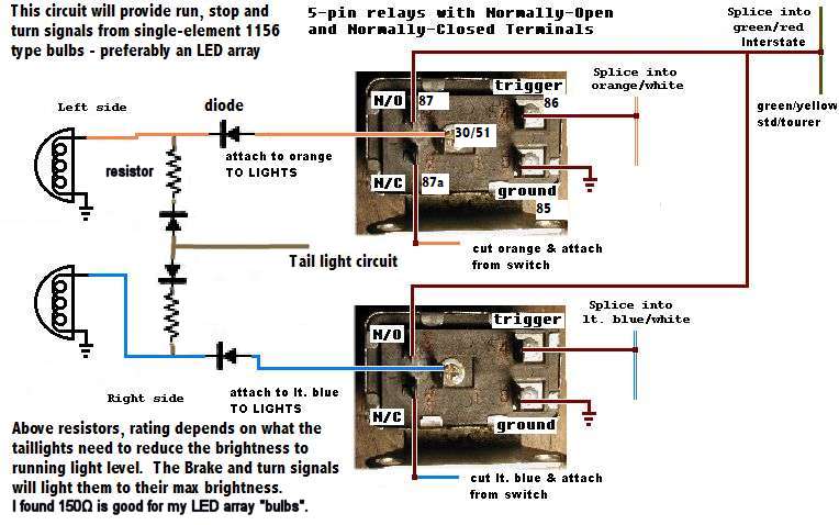 In brief, what the relays do here, is select which circuit powers the bright filiment - selects brake line normally, and selects the turn signal when it's activated on that side by the circuit that powers the running lights in front. Honda designed it so that front running light turns off when you activate the turn signal - that line is used to control the line selection at the relays. With single filiment bulbs as are OEM on the bike in the back, the running light circuit powers that filiment (or LEDs) through a resistor so it's dimmed, while the brake and turn signals run at full power - 12v - so it's brighter then. The diodes in the diagram prevent backfeed between those lines. BTW a handy way to find the ohms needed on the resistors is to use a "pot" in the circuit, dial it until you like the brightness, then measure what you set on the pot with an ohmmeter. Obviously if you have separate run and brake filiments (1157 sockets) then the tail light circuit is unchanged from OEM and you don't need the resistors and diodes on those lines, in the diagram. IOW ignore that part of the diagram. Just run the license plate light circuit (same as the tail light circuit; it's right there in the same fixture) to the running filiment of the dual-filiment marker lights. Also you already know you need to get a digital flasher and do the indicator diode mod. In front, I found amber LED arrays for 1157 sockets, and of course clear lenses also online. I like my indicator now - it flashes red and much brighter than the OEM tungsten bulb. IIRC I didn't need to use resistors in the indicator LED's as they are wired in series with the front marker LED's which have built-in resistors. This circuit has worked perfectly for years on my 2 daily riders - it's proven. |
|
|
|
« Last Edit: February 14, 2019, 07:24:04 AM by MarkT »
|
Logged
|
|
|
|
|
RonW
|
|
« Reply #2 on: January 13, 2019, 06:21:32 PM » |
|
jimblood, perhaps study the wiring on manufactured RTB modules to get a general understanding of the connections that are involved. RTB (run-turn-brake). Several companies manufacture these units. You can download the PDF instructions which illustrate the wiring.
As you're already aware of, diodes are necessary to prevent cross-feed at the turn signal indicator on the dashboard, causing all 4 signals to flash simultaneously, when you activate either right or left signals. Tacking on a brake function to the rear signals inadvertently creates a similar point of cross-feed too. For example, when the left signal is activated, electricity will travel from the left signal's circuit through the left signal's brake input tributary to the right signal's brake light tributary networked as they are to each other. No different than plumbing pipes interconnected to each other. This will cause the right signals to flash when you activate the left signals due to the new point of cross-feed. The simple solution is to splice diodes on the brake light tributaries on the legs of their Y configuration to keep the circuits isolated from each other. This is identical to the diode configuration at the turn signal indicator, albeit, electricity travels in the reverse direction down instead of up the Y, so the diode's have to be orientated accordingly. This design prevents the left signal pulses from cross-feeding over to the right signal circuit specifically at the brake light node, or visa versa. Just something to be aware off. Plug & play RTB modules already anticipate this issue and embed internal diodes in their circuitry.
Some people replace the rear signal sockets with dual filament 1157 sockets, the kind on the front signals, using the low-filament for running lights. Then tacked a brake light function to the high-filament wire. [edit] forgot, you have to over ride the brake input when the corresponding side rear signal is flashing otherwise there won't be dark moments between flashes. The brake light being a steady ON.
|
|
|
|
« Last Edit: January 13, 2019, 06:36:52 PM by RonW »
|
Logged
|
2000 Valkyrie Tourer
|
|
|
|
jimtblood
|
|
« Reply #3 on: February 10, 2019, 10:19:56 AM » |
|
ive been doing some research and i really like the GEN-180-KIT-HON from Custom Dynamics for the rear but they say they wont fit a 2000 Valk.
currently my rear are on as running lights and flash for turn. is that the OEM configuration?
|
|
|
|
|
Logged
|
|
|
|
MarkT
Member
Posts: 5196
VRCC #437 "Form follows Function"
Colorado Front Range - elevation 2.005 km
|
|
« Reply #4 on: February 10, 2019, 10:34:17 AM » |
|
No. OEM is flash for turn only. It's been modded by a PO. You may have 1157 sockets in there already. If so, it's easier - you just need my relay circuit above and some red lenses. You don't need the tail light circuit in the schematic or any of the resistors and diodes - backfeed is impossible, in back. Look at the bulbs - are they tungsten with 2 filiments? If they are LED's - take one out, are there 2 contacts in the bottom of the socket?
|
|
|
|
« Last Edit: February 10, 2019, 10:57:15 AM by MarkT »
|
Logged
|
|
|
|
Jersey
Member
Posts: 545
VRCC #37540
Southern Maryland
|
|
« Reply #5 on: February 10, 2019, 10:59:12 AM » |
|
If you have an I/S, there's a nice mod that can be done to add LEDs and full RTB to the trunk lights. I can't recall who first posted it, but I followed their instructions to separate the lenses. It was VERY easy to do. Heat in the oven for 10 mins at 200F and they pull right apart. Do whichever mod you prefer and reheat to reassemble.
I did this and added a Curt Powered Tail Light Converter # C56190. This worked out well because it also gave me what I needed for the trailer lights.
|
|
|
|
|
Logged
|
Jersey
|
|
|
|
RonW
|
|
« Reply #6 on: February 11, 2019, 12:14:56 AM » |
|
currently my rear are on as running lights and flash for turn. is that the OEM configuration?
If by chance, the PO didn't replace the rear signals with an 1157 dual filament socket, your rear signals are running on a hi-filament, continuously ON. The stock rear signals only have a hi-filament, and that's too much heat for a running light. |
|
|
|
« Last Edit: February 11, 2019, 12:20:57 AM by RonW »
|
Logged
|
2000 Valkyrie Tourer
|
|
|
MarkT
Member
Posts: 5196
VRCC #437 "Form follows Function"
Colorado Front Range - elevation 2.005 km
|
|
« Reply #7 on: February 11, 2019, 06:05:56 AM » |
|
It could have an element in the circuit to reduce the brightness. Like a resistor, particularly for LED "bulbs". That's how the VTX markers are implemented (at least in front don't recall on the back) - dual brightness with an 1156 socket, and how I designed the circuit in the schematic above. I agree on the "too much heat" particularly with tungsten bulbs - I melted the innards on Deerslayer long ago by running markers all the time - and those were 1157's with the dimmer running light that melted them. On a road trip of course - a VOA ride-in to Montrose. LED's run cooler so it's not a problem.
|
|
|
|
|
Logged
|
|
|
|
|
Bambam650
|
|
« Reply #8 on: February 11, 2019, 07:11:41 AM » |
|
I installed a Radiantz LED board in the OEM tailight (which is WAY brighter than tungsten - did this same mod on our Magna too) and replaced the lens with a smoked one. The Radiantz array is expensive - $100 - but there's nothing else like it; they have no competition. It has 128 LEDs and they are REALLY bright. Here it is - doesn't include the fixture: https://www.radiantz.com/VTX-Shadow-Valkyrie-Aero-Sabre-Ace-Retro-p/9012-11.htmI agree 100% with what Mark said about the Radiantz brake light LED board. It is super bright even in the daytime, which is what you want. Well worth the money, IMO. EDIT: FWIW, here's an easy and cheap way to convert any LED to dual intensity. https://chromeglow.com/products/dual-element-circuits-for-led-turn-signals |
|
|
|
« Last Edit: February 11, 2019, 07:19:48 AM by Bambam650 »
|
Logged
|
1997 Standard (Black) original owner, bought new in August 1996
|
|
|
MarkT
Member
Posts: 5196
VRCC #437 "Form follows Function"
Colorado Front Range - elevation 2.005 km
|
|
« Reply #9 on: February 11, 2019, 10:20:24 AM » |
|
Pretty sure what's under the shrink wrap on that piece is a resistor and a diode. That's what I put in the schematic above to get dual intensity out of a single LED light. And how I wire my Highlighter to get run & brake out of one wire feeding to the LED array. |
|
|
|
« Last Edit: February 11, 2019, 10:22:50 AM by MarkT »
|
Logged
|
|
|
|
|
Bambam650
|
|
« Reply #10 on: February 11, 2019, 10:25:13 AM » |
|
Yep, pretty sure that's all it is too. But nice little mod for $5.
|
|
|
|
|
Logged
|
1997 Standard (Black) original owner, bought new in August 1996
|
|
|
|
RonW
|
|
« Reply #11 on: February 11, 2019, 09:22:45 PM » |
|
The literature states it's for led strips, so verify whether it'll work on an led bulb.
|
|
|
|
|
Logged
|
2000 Valkyrie Tourer
|
|
|
|
Bambam650
|
|
« Reply #12 on: February 12, 2019, 05:20:00 AM » |
|
Yes, it will. I used the converter to add running lights to the front turn signals on my Zero DSR (which I converted to LED). Worked great. There are different part numbers depending on many LED's you are trying to control. I'm sure the different part numbers correspond to varying amounts of resistance. I assume that the more LED's you have the more resistance is needed to dim them, but someone should fact check me on that one.
|
|
|
|
« Last Edit: February 12, 2019, 05:29:13 AM by Bambam650 »
|
Logged
|
1997 Standard (Black) original owner, bought new in August 1996
|
|
|
|
Bambam650
|
|
« Reply #13 on: February 13, 2019, 07:00:39 AM » |
|
Mark T, where do I splice into the orange/white and blue/white trigger wires in your electrical diagram? Are they located in the headlight shell?
BTW, does anyone know where I can find a free wiring diagram for a '97 Standard. I didn't see one on the Shop Talk page.
|
|
|
|
« Last Edit: February 13, 2019, 07:18:56 AM by Bambam650 »
|
Logged
|
1997 Standard (Black) original owner, bought new in August 1996
|
|
|
MarkT
Member
Posts: 5196
VRCC #437 "Form follows Function"
Colorado Front Range - elevation 2.005 km
|
|
« Reply #14 on: February 13, 2019, 02:20:17 PM » |
|
Yes that's the easiest place to find them. They also go in the loom that goes to the turn signal sw. I put a pic of the wiring diagram on my web site. http://www.horseapple.com/Valkyrie/Tech_Tips/Valk_Specs/Schematic-Manual/schematic-manual.htmlThere is also a nicely executed one in Excel format I got from Larry Vincent - here's the link I made it available long ago on my site: http://www.horseapple.com/Valkyrie/Tech_Tips/Schematic.xlsI also have a much more verbose one in multiple sheets from RP Brown. Give me a little time I'm working in the shop right now - I'll pkg it up and make it available tonight or in the morning. |
|
|
|
« Last Edit: February 13, 2019, 02:34:26 PM by MarkT »
|
Logged
|
|
|
|
|
|
|
Bambam650
|
|
« Reply #16 on: February 13, 2019, 06:44:29 PM » |
|
Thank you very much, Mark. Much appreciated. You're an invaluable resource.
|
|
|
|
|
Logged
|
1997 Standard (Black) original owner, bought new in August 1996
|
|
|
MarkT
Member
Posts: 5196
VRCC #437 "Form follows Function"
Colorado Front Range - elevation 2.005 km
|
|
« Reply #17 on: February 14, 2019, 07:25:58 AM » |
|
Bump. I did some edits adding to my first post in this thread.
|
|
|
|
|
Logged
|
|
|
|
|
Bambam650
|
|
« Reply #18 on: February 15, 2019, 08:17:54 AM » |
|
Mark, I was finally able to get my head around your relay diagram. What was throwing me was the relays in your set up don’t work the way I typically think of a relay working. I envision a relay being triggered momentarily like using it to power an air horn, for example, and being fed from the #30 terminal, but you sort of reversed all that.
In your arrangement, the relays are activated for most of the time via the trigger wire for the running lights. In fact, the only time the relays aren't activated is when the turn signals are in use. In this situation, power to the running lights (and trigger wire) is cut and the relay switches to the normal inactive mode. So essentially the normally open terminal really becomes normally closed which allows current to flow through from the brake light circuit except when the turn signal is activated. When the turn signal is activated, the trigger wire is deactivated and the normally closed terminal allows current to flow through from the turn signal circuit. I also like the way you used the #87 and #87a terminals as inputs for the two different circuits.
Whew, that’s enough to make anyone’s head hurt. Very ingenious. Kudos to you for figuring that all out.
|
|
|
|
« Last Edit: February 15, 2019, 02:16:13 PM by Bambam650 »
|
Logged
|
1997 Standard (Black) original owner, bought new in August 1996
|
|
|
MarkT
Member
Posts: 5196
VRCC #437 "Form follows Function"
Colorado Front Range - elevation 2.005 km
|
|
« Reply #19 on: February 15, 2019, 01:43:35 PM » |
|
Mark, I was finally able to get my head around your relay diagram. What was throwing me was the relays in your set up don’t work the way I typically think of a relay working. I envision a relay being triggered momentarily like using it to power an air horn, for example, and being fed from the #30 terminal, but you sort of reversed all that.
In your arrangement, the relays are activated for most of the time via the trigger wire for the running lights. In fact, the only time the relays aren't activated is when the turn signals are in use. In this situation, power to the running lights (and trigger wire) is cut and the relay switches to the normal inactive mode. So essentially the normally open terminal really becomes normally closed which allows power to flow through from the brake light circuit except when the turn signal is activated. When the turn signal is activated, the trigger wire is deactivated and the normally closed terminal allows power to flow through from the turn signal circuit. I also like the way you used the #87 and #87a terminals as inputs for the different circuits.
Wew, that’s enough to make anyone’s head hurt. Very ingenious. Kudos to you for figuring that all out.
Yeah you got it. I used the relays in a different way from how they are usually used. It doesn't matter the direction the current goes through the relay. I've been running this circuit for tens of thousands of miles and it's always worked. With quality relays, doesn't hurt to trigger them all the time. I did a backwards logic on how I used a relay to control my fuel transfer solenoid also. It's enabled to be activated only when the power is OFF. Yet it doesn't drain power when not activated. I have a red light on, warning me I'm using power while the ignition is off. It's intended to be only used while refueling. Shuts off when ignition is turned on. It's wired as a "Latch relay" - like a half dozen or so of the 20 relays on Jade. |
|
|
|
« Last Edit: February 15, 2019, 01:48:00 PM by MarkT »
|
Logged
|
|
|
|
|