|
Chrisj CMA
|
 |
« on: September 15, 2021, 10:48:02 AM » |
|
I have two things plugged into my accessories hook up. One is a 12v power outlet for charging cell phones. The other is the stereo amp. I’ve never used the power point except to test to see if the 5A would hold. It was fine and the stereo is used very rarely. Well I m planning on adding an electronic fuel cut off. The acc hook up seems the best place to get power. Since the two items were kind of piggy backed together in the connectors I didn’t want to add more. So I made this crude little circuit board thingy. It bolts to the battery box. 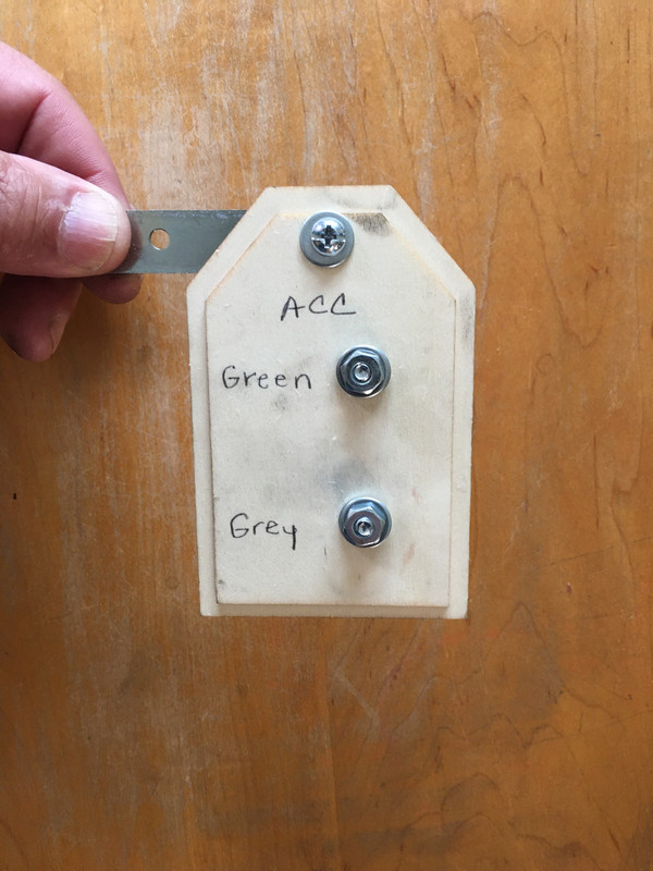 Now the acc hook up is two posts and when I add the fuel switch it will be easy.  |
|
|
|
« Last Edit: September 15, 2021, 11:19:30 AM by Chrisj CMA »
|
 Logged
|
|
|
|
|
Chrisj CMA
|
|
« Reply #1 on: September 15, 2021, 11:07:51 AM » |
|
Maybe I don’t understand what you are doing. Are you powering all of this off of the 5 amp Acc wire, without using relays ?
Everything you see there has been running off the acc wires for years with no relay. It’s really just the amp for the stereo. I have charged a cellphone while playing the stereo, it doesn’t blow the 5A fuse. Once I add the fuel switch. I’ll throw in a 10A fuse |
|
|
|
|
Logged
|
|
|
|
|
Chrisj CMA
|
|
« Reply #2 on: September 15, 2021, 12:00:54 PM » |
|
Maybe I don’t understand what you are doing. Are you powering all of this off of the 5 amp Acc wire, without using relays ?
Everything you see there has been running off the acc wires for years with no relay. It’s really just the amp for the stereo. I have charged a cellphone while playing the stereo, it doesn’t blow the 5A fuse. Once I add the fuel switch. I’ll throw in a 10A fuse I’m no electrical expert. But, that sounds like a lot going thru that one little wire. It’s the same size wire everything else uses. The amplifier draws 2-3 amps. The cell phone is almost nothing and is about never used anyways. The switch can’t be that many amps. I’ll see when I get it. |
|
|
|
|
Logged
|
|
|
|
|
Chrisj CMA
|
|
« Reply #3 on: September 15, 2021, 12:07:34 PM » |
|
Maybe I don’t understand what you are doing. Are you powering all of this off of the 5 amp Acc wire, without using relays ?
Everything you see there has been running off the acc wires for years with no relay. It’s really just the amp for the stereo. I have charged a cellphone while playing the stereo, it doesn’t blow the 5A fuse. Once I add the fuel switch. I’ll throw in a 10A fuse I’m no electrical expert. But, that sounds like a lot going thru that one little wire. It’s the same size wire everything else uses. The amplifier draws 2-3 amps. The cell phone is almost nothing and is about never used anyways. The switch can’t be that many amps. I’ll see when I get it. If I remember the DanMarc is about 2 amps. Ok so I’d be right at the limit with a 5A fuse. But should be clear sailing with a 10A |
|
|
|
|
Logged
|
|
|
|
|
Bagger John - #3785
|
|
« Reply #4 on: September 15, 2021, 12:11:01 PM » |
|
I’m no electrical expert. But, that sounds like a lot going thru that one little wire.
Proper way to do this is to use the ACC wire to switch ANY auxiliary load via relay - regardless of amperage. Said relay switches a fused connection straight from the battery into a distribution point, and individually fused accessory circuits are tied to it. Think Eastern Beaver, Fuze Block, Power Plate, etc. The aim is to prevent any accessories from causing issues with the normal operation of the motorcycle, and to preserve the integrity of its electrical system(s). Should a fault condition occur with an accessory it'll remove itself (via fuse) from the balance of the system without affecting anything else. |
|
|
|
|
Logged
|
|
|
|
|
Chrisj CMA
|
|
« Reply #5 on: September 15, 2021, 12:16:16 PM » |
|
The only thing that will be actually running most of the time is the fuel switch. I’m thinking it will be fine.
|
|
|
|
|
Logged
|
|
|
|
|
pancho
|
|
« Reply #6 on: September 15, 2021, 01:19:00 PM » |
|
One more thing to consider, just by upping the rating of the fuse does not mean the wiring is capable of carrying the 10 amp load. Think about your house wiring.. if a circuit is wired with 12/2 and has a twenty amp breaker, you cannot expect to put a 40 amp breaker in the circuit and draw 30 amps through it. The thirty amp load will overload the wire and give you a thirty or sixty foot fuse which will overheat and catch your house on fire.
|
|
|
|
« Last Edit: September 15, 2021, 01:22:53 PM by pancho »
|
Logged
|
The most expensive things you will purchase, are those things you would not have needed if you had listened and obeyed.
|
|
|
|
Chrisj CMA
|
|
« Reply #7 on: September 15, 2021, 01:46:05 PM » |
|
One more thing to consider, just by upping the rating of the fuse does not mean the wiring is capable of carrying the 10 amp load. Think about your house wiring.. if a circuit is wired with 12/2 and has a twenty amp breaker, you cannot expect to put a 40 amp breaker in the circuit and draw 30 amps through it. The thirty amp load will overload the wire and give you a thirty or sixty foot fuse which will catch your house on fire.
This is what I’d be worried about. I’m sure the max load will be very close to 5A |
|
|
|
|
Logged
|
|
|
|
|
RonW
|
|
« Reply #8 on: September 15, 2021, 02:52:11 PM » |
|
his bike
|
|
|
|
|
Logged
|
2000 Valkyrie Tourer
|
|
|
|
pancho
|
|
« Reply #9 on: September 15, 2021, 02:52:46 PM » |
|
An overheated wire down there could do a lot of damage. I know how rightfully proud you are of the red&white bike. I don’t want to see something happen to it for just a little extra time and money.
My thoughts exactly. I have seen the results many times of putting a larger fuse or breaker in a circuit to carry a load... it isn't pretty.
|
|
|
|
|
Logged
|
The most expensive things you will purchase, are those things you would not have needed if you had listened and obeyed.
|
|
|
|
RonW
|
|
« Reply #10 on: September 15, 2021, 03:03:13 PM » |
|
those were my thoughts too, but christJ stated that the rest of the wires were the same gauge. I actually deleted a previous comment to that effect.
|
|
|
|
|
Logged
|
2000 Valkyrie Tourer
|
|
|
|
Chrisj CMA
|
|
« Reply #11 on: September 15, 2021, 03:40:08 PM » |
|
Ok. Guys. You have me thinking. I feel I am a reasonable guy. And what I’m doing isn’t unreasonable. However, I have a couple of these things laying around and if this simple thing can make my project safer. Why not use one since it’s available. My small problem is I don’t know if this this is the right kind of relay or how to add it to my board. Can any of you advise? 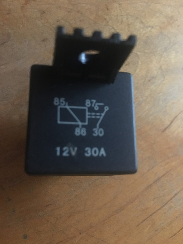  Looks like the connection points are numbered 30, 85, 86, 87 |
|
|
|
« Last Edit: September 15, 2021, 03:49:08 PM by Chrisj CMA »
|
Logged
|
|
|
|
|
Bagger John - #3785
|
|
« Reply #12 on: September 15, 2021, 04:14:04 PM » |
|
That's exactly what you should use (I run that type of relay for all my accessory power feeds, spotlight power, etc). Add a kickback suppressor diode across the relay coils: http://www.bcae1.com/relays.htmSee the section on "quenching diodes". For this application a 1N4007 (available at Radio Shack and a gazillion other electronics parts stores) will work fine. |
|
|
|
|
Logged
|
|
|
|
|
Chrisj CMA
|
|
« Reply #13 on: September 15, 2021, 04:28:20 PM » |
|
That's exactly what you should use (I run that type of relay for all my accessory power feeds, spotlight power, etc). Add a kickback suppressor diode across the relay coils: http://www.bcae1.com/relays.htmSee the section on "quenching diodes". For this application a 1N4007 (available at Radio Shack and a gazillion other electronics parts stores) will work fine. I appreciate the help John, but all that went way over my head. I guess I need instructions in like “baby talk”. Lol. How do I wire this guy in? Our radio shack closed down long time ago but I’ll find a diode. But I still don’t know what to connect to 30,85,86,87 |
|
|
|
« Last Edit: September 15, 2021, 04:40:34 PM by Chrisj CMA »
|
Logged
|
|
|
|
|
Chrisj CMA
|
|
« Reply #14 on: September 15, 2021, 04:52:53 PM » |
|
That's exactly what you should use (I run that type of relay for all my accessory power feeds, spotlight power, etc). Add a kickback suppressor diode across the relay coils: http://www.bcae1.com/relays.htmSee the section on "quenching diodes". For this application a 1N4007 (available at Radio Shack and a gazillion other electronics parts stores) will work fine. I appreciate the help John, but all that went way over my head. I guess I need instructions in like “baby talk”. Lol. How do I wire this guy in? Our radio shack closed down long time ago but I’ll find a diode. But I still don’t know what to connect to 30,85,86,87 I don’t know about the diode. But to wire up the relay 86 is going to go to the Acc wire, 30 to the battery (with a slightly larger gauge wire), 85 to ground, 87 to the items (also larger wire) Hopefully someone else will chime in if I got them mixed up. Thanks MH. 86 goes to ACC wire. Green or grey? Is one hot and one ground? i would assume if so 86 goes to hot? I guess 30 to pos post on battery? |
|
|
|
« Last Edit: September 15, 2021, 04:57:33 PM by Chrisj CMA »
|
Logged
|
|
|
|
|
Bagger John - #3785
|
|
« Reply #15 on: September 15, 2021, 05:02:45 PM » |
|
Thanks MH. 86 goes to ACC wire. Green or grey? Is one hot and one ground? i would assume if so 86 goes to hot?
85 and 86 are the coil wires. Look at the wiring diagram for your bike - Honda wiring codes are usually Grn (Gnd), Blk/Wht, Gry or Brn (+12v). You would put the banded end of the diode to the +12v connection and the non-banded end to Gnd (reverse polarity).  The blue arrow in the picture below points to a typical suppressor diode installation: 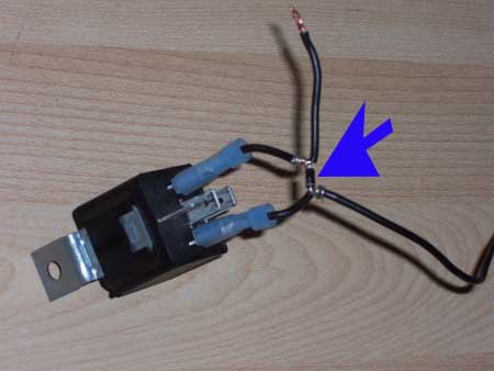 I crimp mine into the ends of the female spade connectors (along with the relay power and ground wires) that will plug onto the relay coil connection. Use heat shrink over the diode. 30 and 87 are your source (from battery through a fuse) and output (to your accessory plate). ETA: The purpose of this diode is to quench what's known as "back EMF" (electromagnetic force) and prevent it from entering the bike's wiring harness where it may damage semiconductors (i.e., the ICM). When you suddenly remove power from a relay, the magnetic field around the coil collapses and generates a large voltage pulse. We're using the same principle in the ignition coils, but THAT "kick-back pulse" is desirable and useful. Putting a diode across the coil in reverse bias will quench the pulse and protect other devices connected to the supply side of the wiring. |
|
|
|
« Last Edit: September 15, 2021, 05:10:08 PM by Bagger John - #3785 »
|
Logged
|
|
|
|
|
Chrisj CMA
|
|
« Reply #16 on: September 15, 2021, 05:09:36 PM » |
|
So, 86 to grey ACC
30 to POS post of battery
85 to gnd
86 to my board where the grey was
Diode from 85-86
Is that right?
|
|
|
|
|
Logged
|
|
|
|
|
Bagger John - #3785
|
|
« Reply #17 on: September 15, 2021, 05:10:58 PM » |
|
So, 86 to grey ACC
30 to POS post of battery
85 to gnd
86 to my board where the grey was
Diode from 85-86
Is that right?
Yes, but BE CAREFUL OF DIODE POLARITY. Band goes to "hot". |
|
|
|
|
Logged
|
|
|
|
|
Chrisj CMA
|
|
« Reply #18 on: September 15, 2021, 05:13:38 PM » |
|
So, 86 to grey ACC
30 to POS post of battery
85 to gnd
86 to my board where the grey was
Diode from 85-86
Is that right?
Yes, but BE CAREFUL OF DIODE POLARITY. Band goes to "hot". Ok great. Since 85 goes to gnd 86 has to be hot so band towards 86! |
|
|
|
|
Logged
|
|
|
|
|
Chrisj CMA
|
|
« Reply #19 on: September 15, 2021, 05:15:19 PM » |
|
I’ll post a pic when it’s done. It’s nice you guys care. Sincerely
|
|
|
|
|
Logged
|
|
|
|
|
Bagger John - #3785
|
|
« Reply #20 on: September 15, 2021, 05:18:43 PM » |
|
In case this drops off the 'Net: http://web.archive.org/web/20040207082226/http://www.rattlebars.com/valkfaq/circuits.htmlChet isn't showing a suppressor diode in his diagrams, and ought to know better. He's one of my nearby neighbors...if he puts his site back online I'll get on him to fix this.  ETA: I went to the Shop Talk page and didn't find a how-to regarding this setup. Most of the commercial distribution blocks already have the required circuitry built in but it would be nice if the DIY gang had a roadmap to follow. Not sure if Willow or the other staff is actively making changes to that area of the site but if they are I'd be glad to contribute some electrical things. |
|
|
|
« Last Edit: September 15, 2021, 05:22:36 PM by Bagger John - #3785 »
|
Logged
|
|
|
|
|
Bagger John - #3785
|
|
« Reply #21 on: September 15, 2021, 05:31:43 PM » |
|
I have never used a diode with the relays. I think I understand what you are saying about the collapsing field putting out a pulse. But being that it’s connected to the Acc wire, wouldn’t there be no where for it to go when the key was turned off ? Being as there would be a break in the circuit.
The gap in the contacts is small enough that a pulse of 500V or greater can jump them when the key goes off. Milliseconds in mechanical dwell time is an eternity (so to speak) in avalanche transit time. I didn't put diodes on the Acc Power or the driving light relays when I configured those circuits on my first Tourer. When I was on a run with the area gang, we'd occasionally stop for gas/eats/water/what have you. During these stops, I'd shut the electrical system off with the key. When I did, I noticed the tach needle jumping to the 2K RPM mark; sometimes higher. Upon arriving home, the circuits were modified to include suppressors. No more erratic tach. I didn't want to chance blowing out the ICM somewhere. |
|
|
|
|
Logged
|
|
|
|
|
Chrisj CMA
|
|
« Reply #22 on: September 15, 2021, 06:13:51 PM » |
|
This HAS been a learning experience. I still need to add the diode. But it’s done and better than that it actually works  |
|
|
|
|
Logged
|
|
|
|
|
pancho
|
|
« Reply #23 on: September 15, 2021, 06:31:27 PM » |
|
Now your cooking with gas!
|
|
|
|
|
Logged
|
The most expensive things you will purchase, are those things you would not have needed if you had listened and obeyed.
|
|
|
|
Bagger John - #3785
|
|
« Reply #24 on: September 15, 2021, 06:41:59 PM » |
|
I'd run the negative lead to a battery ground, but it's coming along nicely.  |
|
|
|
|
Logged
|
|
|
|
|
Chrisj CMA
|
|
« Reply #25 on: September 15, 2021, 06:46:07 PM » |
|
I'd run the negative lead to a battery ground, but it's coming along nicely. Thanks to everyone. Electrical is my worst thing. So now I’m ready for my fuel switch |
|
|
|
|
Logged
|
|
|
|
|
Bagger John - #3785
|
|
« Reply #26 on: September 15, 2021, 06:49:43 PM » |
|
I'd run the negative lead to a battery ground, but it's coming along nicely. Thanks to everyone. Electrical is my worst thing. So now I’m ready for my fuel switch Start here: http://www.autoshop101.com/forms/elec11.pdfShould give you enough basic theory to figure most things out. |
|
|
|
|
Logged
|
|
|
|
|
ridingron
|
|
« Reply #27 on: September 15, 2021, 09:51:50 PM » |
|
My other Honda came from mother Honda (as did many models) With a 30 amp fuse inline with an 18 g. wire. I replaced it with a 25 amp fuse to go to the store for a couple 30 ampers. I blew the 25 amp fuse on the way. Replaced it with the correct 30 amp rated fuse. No problems for 1000s of miles. "shrug"
|
|
|
|
|
Logged
|
|
|
|
|
RonW
|
|
« Reply #28 on: September 15, 2021, 11:09:31 PM » |
|
Some relays have the diode spike suppressor wired internally across 85 - 86. If you can find them.   Others use a resistor across the 85-86. The resistor is wired in parallel like the diode if that makes sense. Google parallel dc circuits.  |
|
|
|
« Last Edit: September 15, 2021, 11:18:16 PM by RonW »
|
Logged
|
2000 Valkyrie Tourer
|
|
|
|
Jims99
|
|
« Reply #29 on: September 16, 2021, 04:55:51 AM » |
|
Just to clarify fuses ( for the non electrical guys). The fuse is to protect the wire, if you up the fuse size the wire can overheat and melt. Please stick with stock size fuses. Could save you from chasing down future problems.
I’ve heard about adding the diode, but never knew why. Thanks for explaining.
|
|
|
|
|
Logged
|
The light at the end of the tunnel, is a train.
99 tourer
00 interstate
97 standard
91 wing
78 trail 70
|
|
|
|
Chrisj CMA
|
|
« Reply #30 on: September 16, 2021, 06:32:22 AM » |
|
Just to clarify fuses ( for the non electrical guys). The fuse is to protect the wire, if you up the fuse size the wire can overheat and melt. Please stick with stock size fuses. Could save you from chasing down future problems.
I’ve heard about adding the diode, but never knew why. Thanks for explaining.
There should be no reason now to change from the 5A. Thanks again |
|
|
|
|
Logged
|
|
|
|
|
Shakie NC
|
|
« Reply #31 on: September 17, 2021, 01:09:48 PM » |
|
This post has nothing to do with wiring, but more about the paint on your rear shocks where did you get it. I want to pint mine, that looks like it will hold up. any help you willing to share would be appreciated thanks.
|
|
|
|
|
Logged
|
Shakie NC
|
|
|
|
Chrisj CMA
|
|
« Reply #32 on: September 17, 2021, 01:14:18 PM » |
|
This post has nothing to do with wiring, but more about the paint on your rear shocks where did you get it. I want to pint mine, that looks like it will hold up. any help you willing to share would be appreciated thanks.
I just went to AutoZone and got some gloss black automotive spray paint. Nothing special. Lots of sanding before painting but it’s held for years now with no issues I also have faux carbon fiber tape and red pin strip on it 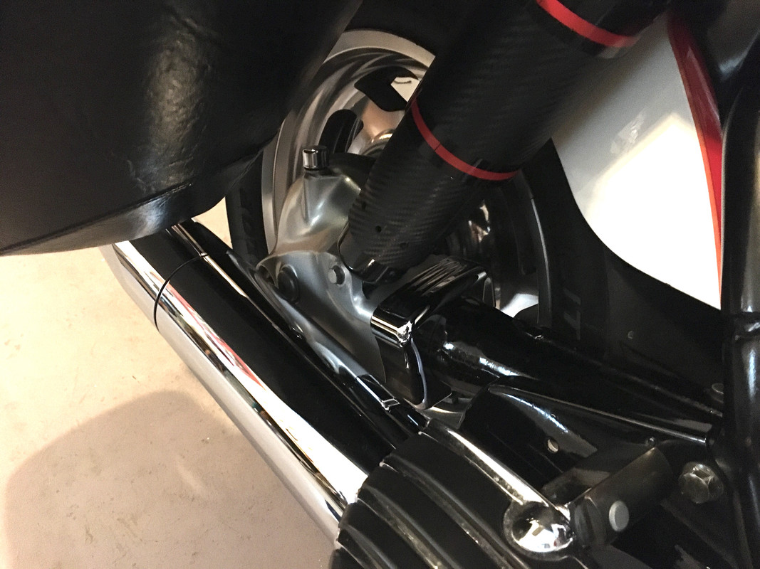 |
|
|
|
« Last Edit: September 17, 2021, 03:07:12 PM by Chrisj CMA »
|
Logged
|
|
|
|
|
Avanti
|
|
« Reply #33 on: September 19, 2021, 06:13:47 PM » |
|
Thanks MH. 86 goes to ACC wire. Green or grey? Is one hot and one ground? i would assume if so 86 goes to hot?
85 and 86 are the coil wires. Look at the wiring diagram for your bike - Honda wiring codes are usually Grn (Gnd), Blk/Wht, Gry or Brn (+12v). You would put the banded end of the diode to the +12v connection and the non-banded end to Gnd (reverse polarity). The blue arrow in the picture below points to a typical suppressor diode installation: I crimp mine into the ends of the female spade connectors (along with the relay power and ground wires) that will plug onto the relay coil connection. Use heat shrink over the diode. 30 and 87 are your source (from battery through a fuse) and output (to your accessory plate). ETA: The purpose of this diode is to quench what's known as "back EMF" (electromagnetic force) and prevent it from entering the bike's wiring harness where it may damage semiconductors (i.e., the ICM). When you suddenly remove power from a relay, the magnetic field around the coil collapses and generates a large voltage pulse. We're using the same principle in the ignition coils, but THAT "kick-back pulse" is desirable and useful. Putting a diode across the coil in reverse bias will quench the pulse and protect other devices connected to the supply side of the wiring. I do not think that any of the relays used on the Interstate are set up in this fashion. Is there something different in the way they are used or there placement? |
|
|
|
|
Logged
|
|
|
|
|