|
TearlessTom
|
 |
« on: September 27, 2010, 03:52:11 PM » |
|
I am suppose to be leaving in two days to go on vacation to ride the Ozarks for a week or so BUT
MY BIKE WANT START!!!
I mean completely dead. No power to anything.!!!!
I got home from running some errands on the bike, she was running perfectly!
Turned it off by the kill switch like I normally do, turned off the ignition. Went to start it back up and nothing. No power anywhere.
I pulled the side cover and checked the fuses. The main 30amp fuse is blown. I replaced it.
I now have power to my fusible link, but when I turn the ignition switch on I get nothing. No headlight, tail light no turn signal and no start. No indication of power going through the ignition at all.
I pulled the tank off and unplugged the ignition switch. I am getting .25 volts on two of the leads going to the ignition switch...
I am at a dead end !
I have no idea how to proceed from here.
Any and all help welcome.
|
|
|
|
|
 Logged
|
|
|
|
Skinhead
Member

Posts: 8752
J. A. B. O. A.
Troy, MI
|
|
« Reply #1 on: September 27, 2010, 04:00:49 PM » |
|
Did you turn the kill switch back on again? (don't ask how I know this)
|
|
|
|
|
Logged
|
 Troy, MI |
|
|
|
TearlessTom
|
|
« Reply #2 on: September 27, 2010, 04:02:25 PM » |
|
Did you turn the kill switch back on again? (don't ask how I know this)
Yes, and I know how you know this, the same way I do.. Even if the kill switch was off, I would still have lights, and turn signals, I have no power whatsover getting through.. Ive checked the fuses and there all good. |
|
|
|
|
Logged
|
|
|
|
Skinhead
Member
Posts: 8752
J. A. B. O. A.
Troy, MI
|
|
« Reply #3 on: September 27, 2010, 04:04:28 PM » |
|
sorry I just reread your post. Is there any chance the main fuse blew again?
|
|
|
|
|
Logged
|
Troy, MI |
|
|
Skinhead
Member
Posts: 8752
J. A. B. O. A.
Troy, MI
|
|
« Reply #4 on: September 27, 2010, 04:08:10 PM » |
|
Have you checked the starter relay? Something caused your 30 to blow. Sorry I don't remember the symptoms when the starter relay is all corroded/melted. Are we talking standard/tourer or IS?
|
|
|
|
|
Logged
|
Troy, MI |
|
|
Airetime
Member
Posts: 156
U Never See a Valk Parked @ a Psychiatrist Office
Anacortes, WA
|
|
« Reply #5 on: September 27, 2010, 04:09:39 PM » |
|
I am suppose to be leaving in two days to go on vacation to ride the Ozarks for a week or so BUT
MY BIKE WANT START!!!
I mean completely dead. No power to anything.!!!!
I got home from running some errands on the bike, she was running perfectly!
Turned it off by the kill switch like I normally do, turned off the ignition. Went to start it back up and nothing. No power anywhere.
I pulled the side cover and checked the fuses. The main 30amp fuse is blown. I replaced it.
I now have power to my fusible link, but when I turn the ignition switch on I get nothing. No headlight, tail light no turn signal and no start. No indication of power going through the ignition at all.
I pulled the tank off and unplugged the ignition switch. I am getting .25 volts on two of the leads going to the ignition switch...
I am at a dead end !
I have no idea how to proceed from here.
Any and all help welcome.
My .02 is on a bad ground either at the battery or on the frame.  |
|
|
|
|
Logged
|
|
|
|
|
CajunRider
|
|
« Reply #6 on: September 27, 2010, 04:11:17 PM » |
|
With a blown 30 amp fuse, I'd suspect a major ground short somewhere, which can blow many more of the smaller individual fuses before the main 30 amp went.
Check ALL fuses and re-check the 30 amp to make sure they are all OK.
If all fuses are good, check all the safety switches (Run/Stop switch, clutch switch, gear/neutral switch, kickstand switch... etc...) Just flick them back-forth a few times and try to start again... it seems to be a new problem, so could be just a bad/dirty connection.
Since the 30 amp blew, it'd be a good idea to check the battery leads (and starter motor leads) for any possible shorts to the frame. A short there would probably make quite a visible arching mark, so it should be easy to find if that's the problem.
If there's nothing obvious, it can be much harder to find... so check all fuses and main battery cables... and hope for the best.
I know how you feel... been there before (was a cage... but same issues...).
Good luck.
|
|
|
|
|
Logged
|
Sent from my Apple IIe
|
|
|
fudgie
Member
Posts: 10651
Better to be judged by 12, then carried by 6.
Huntington Indiana

|
|
« Reply #7 on: September 27, 2010, 05:08:21 PM » |
|
Battery?
|
|
|
|
|
Logged
|
 Now you're in the world of the wolves... And we welcome all you sheep... VRCC-#7196 VRCCDS-#0175 DTR PGR |
|
|
|
Thunderbolt
|
|
« Reply #8 on: September 27, 2010, 05:28:33 PM » |
|
My bet is that the terminals got too hot and melted.
|
|
|
|
|
Logged
|
|
|
|
|
TearlessTom
|
|
« Reply #9 on: September 27, 2010, 05:38:13 PM » |
|
Okay my battery terminals are good, my 30Amp is good, My 5,10, &15 amp fuses are good. I am getting battery power through the main block, to the fusible link. I have 2.5-3 volts on 2 of the 4 wires that go to the ignition switch, and on the back of the ignition switch I get the same 22.5-3 volts on two leads.
Just nothing happens when I turn the switch on... I mean nothing.
I shot some contact cleaner in through the key hole till it ran out the back. Still nothing.
It acts as if a bad contact in the ignition switch but I can t believe it went out with out any warning what so ever. Bike has been running perfectly. No electrical problems other than burned out turn signal bulbs etc.
I cant find the ignition switch on the HDL schematics. If anyone can locate it let me know.
An y other ideas.
|
|
|
|
|
Logged
|
|
|
|
|
TearlessTom
|
|
« Reply #10 on: September 27, 2010, 05:44:55 PM » |
|
Rechecked the battery ground all looks good. no corrosion or loose.
|
|
|
|
|
Logged
|
|
|
|
eric in md
Member
Posts: 2495
ride hard now we all can rest when were gone !!!
in the mountains .......cumberland md
|
|
« Reply #11 on: September 27, 2010, 05:45:54 PM » |
|
starter button service.. ? man i hate this for you ..
|
|
|
|
|
Logged
|
|
|
|
|
paps350
|
|
« Reply #12 on: September 27, 2010, 06:24:49 PM » |
|
I don't have a wiring schematic in front of me but I would think it is somewhere before the ignition switch or lights would work, You said you have voltage before the fuseable link but is there voltage after it? I'm not sure of your voltage readings, they should read 12 to 14 volts at those terminals.
|
|
|
|
|
Logged
|
|
|
|
|
Madmike
|
|
« Reply #13 on: September 27, 2010, 06:25:48 PM » |
|
Okay my battery terminals are good, my 30Amp is good, My 5,10, &15 amp fuses are good. I am getting battery power through the main block, to the fusible link. I have 2.5-3 volts on 2 of the 4 wires that go to the ignition switch, and on the back of the ignition switch I get the same 22.5-3 volts on two leads. schematicSeems that your battery voltage is low or you have very high resistance somewhere in the feed to the ignition switch. Why do you only have 3 volts at the ignition switch - it should be battery voltage?? If the battery voltage is good then it would seem that you are getting excessive voltage drop somewhere which is an indication of high resistance. If you find out where the drop is occurring in the circuit then you will find the high resistance. What voltage do you have across the battery posts?? What voltage do you have from the positive battery post to ground?? You may have a short to ground that blew the 30 AMP and the battery was drawn down enough that it is now virtually dead. |
|
|
|
« Last Edit: September 27, 2010, 06:28:07 PM by Madmike »
|
Logged
|
|
|
|
|
FryeVRCCDS0067
|
|
« Reply #14 on: September 27, 2010, 06:45:07 PM » |
|
Check your starter relay if you haven't already. The harness going into the top of it gets corroded and overheats. Also the fuse in the top of the relay could be blown. On my 97 the fuse was corroded so bad it ruined the relay. The problem started out with the bike dying at stop signs and then not turning over when I would try to restart it. Check it out, it's under the right side cover. Good luck.
|
|
|
|
|
Logged
|
"Extremism in the defense of liberty is no vice. And... moderation in the pursuit of justice is no virtue.'' -- Barry Goldwater, Acceptance Speech at the Republican Convention; 1964  |
|
|
|
TearlessTom
|
|
« Reply #15 on: September 27, 2010, 06:52:57 PM » |
|
I don't have a wiring schematic in front of me but I would think it is somewhere before the ignition switch or lights would work, You said you have voltage before the fuseable link but is there voltage after it? I'm not sure of your voltage readings, they should read 12 to 14 volts at those terminals.
Okay my battery terminals are good, my 30Amp is good, My 5,10, &15 amp fuses are good. I am getting battery power through the main block, to the fusible link. I have 2.5-3 volts on 2 of the 4 wires that go to the ignition switch, and on the back of the ignition switch I get the same 22.5-3 volts on two leads. schematicSeems that your battery voltage is low or you have very high resistance somewhere in the feed to the ignition switch. Why do you only have 3 volts at the ignition switch - it should be battery voltage?? If the battery voltage is good then it would seem that you are getting excessive voltage drop somewhere which is an indication of high resistance. If you find out where the drop is occurring in the circuit then you will find the high resistance. What voltage do you have across the battery posts?? What voltage do you have from the positive battery post to ground?? You may have a short to ground that blew the 30 AMP and the battery was drawn down enough that it is now virtually dead. Sorry I guess I wasn't clear, The battery has 12+ volt on it. I had it hooked to the trickle charger while trying to trouble shoot as to not run it down. I have 12+ vollts across the fusible link. It is at the ignition switch I am getting 2.5 to 3, which is I am thinking power for the switch to make the connection. I don't think the full 12 volts should be running across the ignition switch. should it. |
|
|
|
|
Logged
|
|
|
|
gordonv
Member
Posts: 5766
VRCC # 31419
Richmond BC
|
|
« Reply #16 on: September 27, 2010, 07:14:26 PM » |
|
I think this is easy. First you HAVE to get the manual. You NEED the schematic also.
The manual has the info to test your switch.
I would agree that it's either the switch or something before the switch. That is why nothing works after it. You need the manual to show you which leads while have continuity between what leads at the switch, sec 19-19. Schematic is at 20-11 (20-0 pullout).
You didn't say which model/year you had. The manual shows CF, 97-98 C/CT and 99' newer. I looked it over, but didn't want to spend too much time, because I don't know if I'm looking at the right one.
I would also agree you should have battery voltage at at least one terminal at the switch, and if you don't, then the problem is before the switch. There is the main fuse, 55A, is that the fusible link? there should be battery voltage at both ends.
|
|
|
|
« Last Edit: September 27, 2010, 07:25:12 PM by gordonv »
|
Logged
|
1999 Black with custom paint IS   |
|
|
gordonv
Member
Posts: 5766
VRCC # 31419
Richmond BC
|
|
« Reply #17 on: September 27, 2010, 07:20:32 PM » |
|
Yes, switch DOES have 12 V, it comes through the 30A fuse, Red wire. This is for the run power (lights) and the ACC pwr.
The main fuse, 55A, is for power for the battery, nothing for the rest.
|
|
|
|
« Last Edit: September 27, 2010, 07:29:52 PM by gordonv »
|
Logged
|
1999 Black with custom paint IS |
|
|
Walküre
Member
Posts: 1270
Nothing beats a 6-pack!
Oxford, Indiana
|
|
« Reply #18 on: September 27, 2010, 07:24:51 PM » |
|
Sorry I guess I wasn't clear, The battery has 12+ volt on it. I had it hooked to the trickle charger while trying to trouble shoot as to not run it down.
I have 12+ vollts across the fusible link.
It is at the ignition switch I am getting 2.5 to 3, which is I am thinking power for the switch to make the connection. I don't think the full 12 volts should be running across the ignition switch. should it.
If you "have 12 volts across the fusible link", then your link is bad. By "across", if you mean you held your voltmeter leads one on each side of the link, you should read 0 volts, because there would be continuity across the link. If you mean that you hold ONE lead to ground, and the other to one side of the link, and get 12 volts, then hold that lead to the OTHER side of the link and still get 12 volts, the link is good. But the most common description of "reading across" is a lead on each side of whatever is being tested. Hope that makes sense. And conversely so for the switch. With the switch "off", you would read 12 volts "across" the switch - one lead on each side of it. If it was closed, you should read 0 across it. Or alternatively, with switch off, one lead on ground, the other on one side of switch, you get 12 volts, the lead on other side of switch, 0 volts. With switch "closed" or "on", you would get 12 volts on each side of switch, with other lead to ground. Roger |
|
|
|
|
Logged
|
2000 Valkyrie Standard
1999 Valkyrie Interstate
2000 HD Dyna Wide Glide FXDWGRoger Phillips Oxford, IN VRCC #31978 Yeah, what she said...
|
|
|
gordonv
Member
Posts: 5766
VRCC # 31419
Richmond BC
|
|
« Reply #19 on: September 27, 2010, 07:28:19 PM » |
|
Thank you for the clarification, we need to make sure we are all talking the same thing.
Unless you are testing a dead circuit, for continuity using an Ohm meter, we are talking a volt meter with the negative lead to ground, and using the positive lead looking for voltage at points (did I say this right, I'll edit/correct if need be to clarify)
|
|
|
|
|
Logged
|
1999 Black with custom paint IS |
|
|
Walküre
Member
Posts: 1270
Nothing beats a 6-pack!
Oxford, Indiana
|
|
« Reply #20 on: September 27, 2010, 07:42:08 PM » |
|
Thank you for the clarification, we need to make sure we are all talking the same thing.
Unless you are testing a dead circuit, for continuity using an Ohm meter, we are talking a volt meter with the negative lead to ground, and using the positive lead looking for voltage at points (did I say this right, I'll edit/correct if need be to clarify)
Exactly right! And as you said, just a way to make sure we are talking the same language. To-may-to, to-mah-to, but crucial to troubleshooting. After 30 years as an Electronics Tech, reading 12 volts "across" the link is bad, but reading 12 volts at both sides, is good. Sounds like you have a good handle on what you are looking at. Just clarifying it in my mind. I'll take a look when I get home, at the schematic, if you haven't gotten some answers by then. Roger |
|
|
|
|
Logged
|
2000 Valkyrie Standard
1999 Valkyrie Interstate
2000 HD Dyna Wide Glide FXDWGRoger Phillips Oxford, IN VRCC #31978 Yeah, what she said...
|
|
|
R J
Member
Posts: 13380
DS-0009 ...... # 173
Des Moines, IA
|
|
« Reply #21 on: September 27, 2010, 07:51:47 PM » |
|
The 1st place I would look is here.  If it looks like this then you need this from and Honda place. 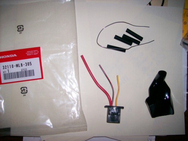 This unit is for an older Gold Wing, so ya have to move the red wire to match the bike. NO big deal............ |
|
|
|
|
Logged
|
44 Harley ServiCar   |
|
|
|
FryeVRCCDS0067
|
|
« Reply #22 on: September 27, 2010, 08:04:33 PM » |
|
As an industrial electrician I know how long it can take to trace down an electrical problem with a meter. I've done it with many people looking over my shoulder when the down time was costing thousands of dollars an hour. Sometimes it pays to skip ahead to probable trouble spots before you resort to going the long way around. Starter relay pics and threads. http://www.valkyrieforum.com/forum/tech_archive.cgi?read=1359761http://www.rattlebars.com/mtz/starter.htmlOn the 2'nd link go to the lower half of the page to see the section on starter relay problems and solutions. This was written up by some very sharp VRCC members quite a while ago. It may not be your problem but the symptoms are pretty similar. Frye |
|
|
|
|
Logged
|
"Extremism in the defense of liberty is no vice. And... moderation in the pursuit of justice is no virtue.'' -- Barry Goldwater, Acceptance Speech at the Republican Convention; 1964 |
|
|
|
TearlessTom
|
|
« Reply #23 on: September 27, 2010, 08:05:29 PM » |
|
Thank you for the clarification, we need to make sure we are all talking the same thing.
Unless you are testing a dead circuit, for continuity using an Ohm meter, we are talking a volt meter with the negative lead to ground, and using the positive lead looking for voltage at points (did I say this right, I'll edit/correct if need be to clarify)
Exactly right! And as you said, just a way to make sure we are talking the same language. To-may-to, to-mah-to, but crucial to troubleshooting. After 30 years as an Electronics Tech, reading 12 volts "across" the link is bad, but reading 12 volts at both sides, is good. Sounds like you have a good handle on what you are looking at. Just clarifying it in my mind. I'll take a look when I get home, at the schematic, if you haven't gotten some answers by then. Roger Okay so you have found out thaqt eletronics is a second language for me. It reads 12 .25 volts to ground on ether side. It reads zero volts across the two. It read .25 - .5 at the backside of teh ignition switch on two poles, zero on the other two poles. l I have a book I am breakng it out to see which wires are what. |
|
|
|
|
Logged
|
|
|
|
|
TearlessTom
|
|
« Reply #24 on: September 27, 2010, 08:07:06 PM » |
|
The 1st place I would look is here. If it looks like this then you need this from and Honda place. This unit is for an older Gold Wing, so ya have to move the red wire to match the bike. NO big deal............ Yep looked there 1st, all is good. Thanks RJ |
|
|
|
|
Logged
|
|
|
|
|
FryeVRCCDS0067
|
|
« Reply #25 on: September 27, 2010, 08:11:14 PM » |
|
The 1st place I would look is here. If it looks like this then you need this from and Honda place. This unit is for an older Gold Wing, so ya have to move the red wire to match the bike. NO big deal............ Yep, I think you helped me through it when my cooked.  |
|
|
|
|
Logged
|
"Extremism in the defense of liberty is no vice. And... moderation in the pursuit of justice is no virtue.'' -- Barry Goldwater, Acceptance Speech at the Republican Convention; 1964 |
|
|
gordonv
Member
Posts: 5766
VRCC # 31419
Richmond BC
|
|
« Reply #26 on: September 27, 2010, 08:24:02 PM » |
|
First so we can follow along which model and year Valk do you have?
I think your right, the problem is around the switch.
If you have the manual, then it shows at page 19-19 to pull the connector off the back of the ignition switch and check for continuity between .... I didn't look hard enough, but that should be between the points on the switch, not the connector.
The connector should have what, 4 or 5 wires, of which one is Red. This lead should have 12 volts. With these 2 things done, you will KNOW if the propblem is before or after the switch, or the switch itself. From here we can move further along.
Like the other post, follow the thread which will show some short cuts. But from my limited (years worth) knowledge of doing this, this is your best bet.
|
|
|
|
« Last Edit: September 28, 2010, 07:29:36 AM by gordonv »
|
Logged
|
1999 Black with custom paint IS |
|
|
|
TearlessTom
|
|
« Reply #27 on: September 27, 2010, 08:30:37 PM » |
|
As an industrial electrician I know how long it can take to trace down an electrical problem with a meter. I've done it with many people looking over my shoulder when the down time was costing thousands of dollars an hour. Sometimes it pays to skip ahead to probable trouble spots before you resort to going the long way around. Starter relay pics and threads. http://www.valkyrieforum.com/forum/tech_archive.cgi?read=1359761http://www.rattlebars.com/mtz/starter.htmlOn the 2'nd link go to the lower half of the page to see the section on starter relay problems and solutions. This was written up by some very sharp VRCC members quite a while ago. It may not be your problem but the symptoms are pretty similar. Frye 12.25 volts to ground on two spades zero voltage two remaining two spades. Not fried looks good no corosion. |
|
|
|
|
Logged
|
|
|
|
|
Bugslayer
|
|
« Reply #28 on: September 27, 2010, 08:45:00 PM » |
|
Holler if you need something scanned from the Shop Manual. I can either post it here or e-mail it to ya.
|
|
|
|
|
Logged
|
|
|
|
|
TearlessTom
|
|
« Reply #29 on: September 27, 2010, 08:51:20 PM » |
|
Holler if you need something scanned from the Shop Manual. I can either post it here or e-mail it to ya.
Thanks, I have a PDF copy and a Clymers for what it is worth. Just reading section 19 |
|
|
|
|
Logged
|
|
|
|
|
TearlessTom
|
|
« Reply #30 on: September 27, 2010, 09:01:32 PM » |
|
I think this is easy. First you HAVE to get the manual. You NEED the schematic also.
The manual has the info to test your switch.
I would agree that it's either the switch or something before the switch. That is why nothing works after it. You need the manual to show you which leads while have continuity between what leads at the switch, sec 19-19. Schematic is at 20-11 (20-0 pullout).
You didn't say which model/year you had. The manual shows CF, 97-98 C/CT and 99' newer. I looked it over, but didn't want to spend too much time, because I don't know if I'm looking at the right one.
I would also agree you should have battery voltage at at least one terminal at the switch, and if you don't, then the problem is before the switch. There is the main fuse, 55A, is that the fusible link? there should be battery voltage at both ends.
I have a 97 Tourer. I checked I think like it and you said. At the back of the ignition (key) switch I am getting .25+/- volts. On the red. At the quick connect on the red I am getting the same .25V to ground. I am getting ?continuity? (zero reading) between the spades on the key side and .25 between the spades on the quick connect side on two spades when checking with the red wire if that makes any sense. The quick connect I am referring to is the one in section 19-19 |
|
|
|
|
Logged
|
|
|
|
|
Bugslayer
|
|
« Reply #31 on: September 27, 2010, 09:03:02 PM » |
|
Holler if you need something scanned from the Shop Manual. I can either post it here or e-mail it to ya.
Thanks, I have a PDF copy and a Clymers for what it is worth. Just reading section 19 Good luck. I hope ya find the problem. |
|
|
|
|
Logged
|
|
|
|
fudgie
Member
Posts: 10651
Better to be judged by 12, then carried by 6.
Huntington Indiana
|
|
« Reply #32 on: September 28, 2010, 05:21:01 AM » |
|
Can ya push start it?
|
|
|
|
|
Logged
|
Now you're in the world of the wolves... And we welcome all you sheep... VRCC-#7196 VRCCDS-#0175 DTR PGR |
|
|
|
TearlessTom
|
|
« Reply #33 on: September 28, 2010, 05:33:14 AM » |
|
Can ya push start it?
Havent tried yet but doubt it as I am getting no electricty through the system |
|
|
|
|
Logged
|
|
|
|
fudgie
Member
Posts: 10651
Better to be judged by 12, then carried by 6.
Huntington Indiana
|
|
« Reply #34 on: September 28, 2010, 05:44:00 AM » |
|
Can ya push start it?
Havent tried yet but doubt it as I am getting no electricty through the system worth a shot. Maybe it'll kick something and it will start with the button the next time. |
|
|
|
|
Logged
|
Now you're in the world of the wolves... And we welcome all you sheep... VRCC-#7196 VRCCDS-#0175 DTR PGR |
|
|
X Ring
Member
Posts: 3626
VRCC #27389, VRCCDS #204
The Landmass Between Mobile And New Orleans
|
|
« Reply #35 on: September 28, 2010, 06:10:33 AM » |
|
Tom, If you haven't figured it out by Thursday night, give me a shout and I can come help you Friday, Saturday or Sunday.
Marty
|
|
|
|
|
Logged
|
People are more passionately opposed to wearing fur than leather because it's safer to harass rich women than bikers.  |
|
|
|
cef2lion
|
|
« Reply #36 on: September 28, 2010, 06:17:42 AM » |
|
Check out the wiring diagrams off this link on the left side for the STD/Tour. They really helped me out with an issue I had with my I/S. The S1 show main ppower distribution. S4 is the starting circuit. If you follow the wire off the 30amp fuse. It goes to the IGN switch. After the key is on power is sent to the fuse box fuses. If you are good with 12 volt on both sides of the fuse. Check for 12V both sides of the fuses in the fuse box with key on. If no power you might have an issue with the IGN switch.
On my '98 STD every so often I had an issue after killing bike with kill switch. When on a grade I often use the kill switch as I need to keep brake applied and keep bike upright and don't have a free hand to reach over and shut off the key. When I used the kill switch a few times it acted up and nothing happened when I tried to start it. I can't recall if I had lights. I of and on the kill switch a few times. Press the starter button a few times. Make sure the kick stand is up and its in neutral.
Good luck. If you trace and test for power off those diagrams you might be able to isolate the issue.
Craig
|
|
|
|
|
Logged
|
|
|
|
gordonv
Member
Posts: 5766
VRCC # 31419
Richmond BC
|
|
« Reply #37 on: September 28, 2010, 07:29:03 AM » |
|
The manual has the info to test your switch.
after it. You need the manual to show you which leads while have continuity between what leads at the switch, sec 19-19. Schematic is at 20-11 (20-0 pullout).
I have a 97 Tourer. I checked I think like it and you said. At the back of the ignition (key) switch I am getting .25+/- volts. On the red. At the quick connect on the red I am getting the same .25V to ground. I am getting ?continuity? (zero reading) between the spades on the key side and .25 between the spades on the quick connect side on two spades when checking with the red wire if that makes any sense. The quick connect I am referring to is the one in section 19-19 Lets clarify for a second. You have NO electricity when you turn your bike on with the switch. So the problem is “switch related”, no power going to the bike, so don’t bother with the kill switch or push starting. It’s switch related, like if the battery is dead, or a wire cut after the switch, the problem is with the ignition switch circuit. You wrote you had 12.5V at a spade, was this at the switch or the fuse? There are two things to test at the switch. The switch itself, and the connector. You are saying at the back of the switch you are getting .25+/- V. First, test the connector, we need 12 V at the red lead. If you have that, then test the switch. In the manual at page 19-19 it shows how to test the switch. Using the key, you should have/have no continuity between the pins it tells you. After the above results we can move on. No V at the connector, then it’s between there and the battery. No continuity, then the switch. Switch tests out positive, then we move to the next stage from there. Please let us know the results. |
|
|
|
|
Logged
|
1999 Black with custom paint IS |
|
|
|
cef2lion
|
|
« Reply #38 on: September 28, 2010, 08:09:39 AM » |
|
|
|
|
|
|
Logged
|
|
|
|
gordonv
Member
Posts: 5766
VRCC # 31419
Richmond BC
|
|
« Reply #39 on: September 28, 2010, 08:21:20 AM » |
|
I like that, it would jump one extra lenght to the next stag of testing.
Shows which points on the fuse block would have 12V with the ignition turned on. I think you need to take the tank off to get to the ignition switch, so it's easier to get to the side cover instead.
|
|
|
|
|
Logged
|
1999 Black with custom paint IS |
|
|
|


