This thread will discuss the installation of the Rostra 250 cruise control on Lady Val, my 1998 Valkyrie Tourer. This was done over the winter of 2015-16. I have seen write ups of such installs in Interstates but not so on the more confined spaces of Standards and Tourers. This is by far the most complex enhancement to the Valk that I have yet to attempt, and the instructions provided by Rostra suck big time. To be somewhat fair, Rostra supports installation of these units in cars and trucks, not motorcycles. I have read that their help line will not even talk to you if they learn that the unit is going into a motorcycle.
This cruise control operates with a servo motor and is not vacuum operated. I did a shiny desmog several years ago in preperation of a cruise control install, but did not care for the CSS-100 unit and did not go further.
The four physical components I purchased were:
250-1223 Rostra Global Cruise
250-3592 Dash Mount Control with engaged light
250-4165 Speed Signal Generator
250-3093 Set of 10 extra Speed Signal Generator magnets
The total cost was $327.
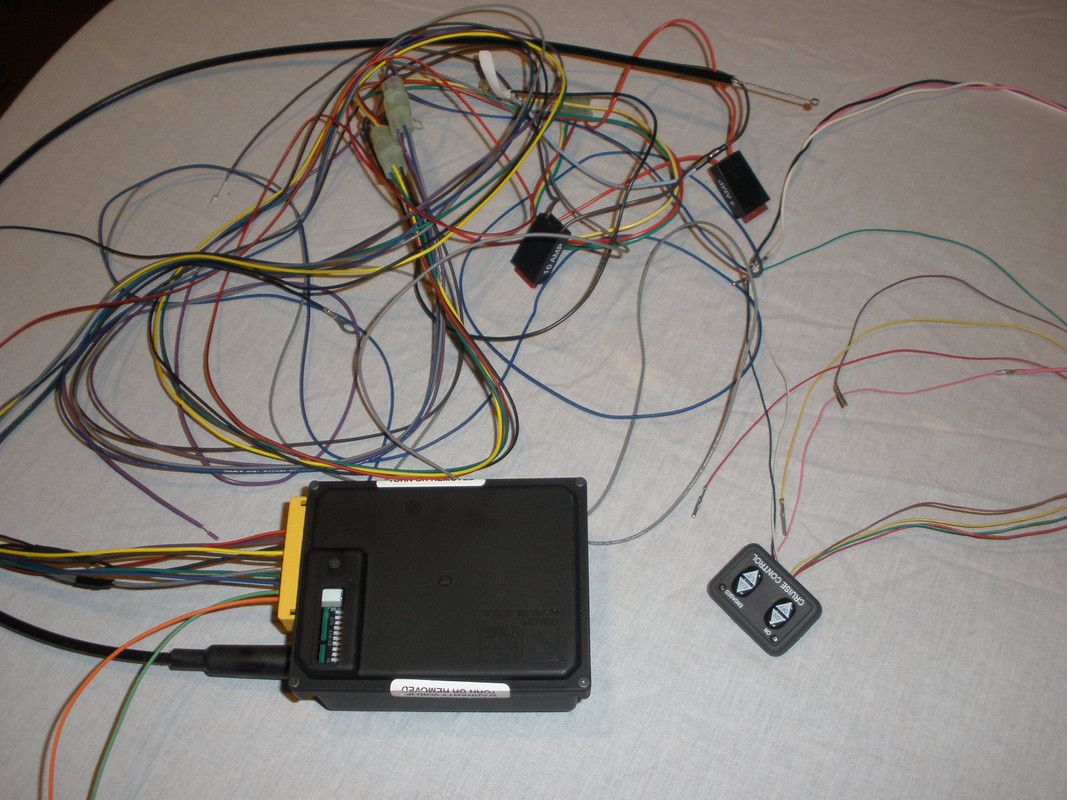
Below is a picture of the Global Cruise with all the wiring harness covers removed. Again, this cruise control is ment to go under the hood of a cage and the harness was constructed to do just that. For a motorcycle installation, it made sense to deal with the ten individual wires. To the right is the Dash Mount Control which had the usual cruise control functions. It has nine wires leaving the unit.
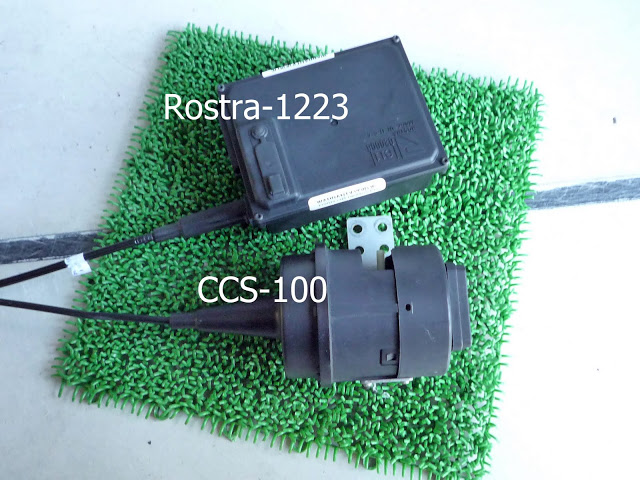
Here is a comparison picture of the Global Cruise vs. the CCS-100 which many of us have installed on our Valks. I picked this picture off the internet. Many more pictures can be found by Googling "rostra 250 images".
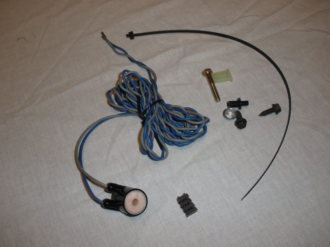
Don't panic yet, we just have to figure each what wire is for and take our time. Pictured next is the Speed Signal Generator which consists of four magnets and a pick up coil. I at first used only three magnets, but after road tests we ended up with nine installed. That required purchasing the kit of ten additional magnets.
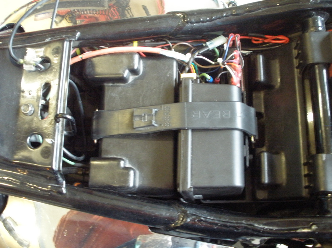
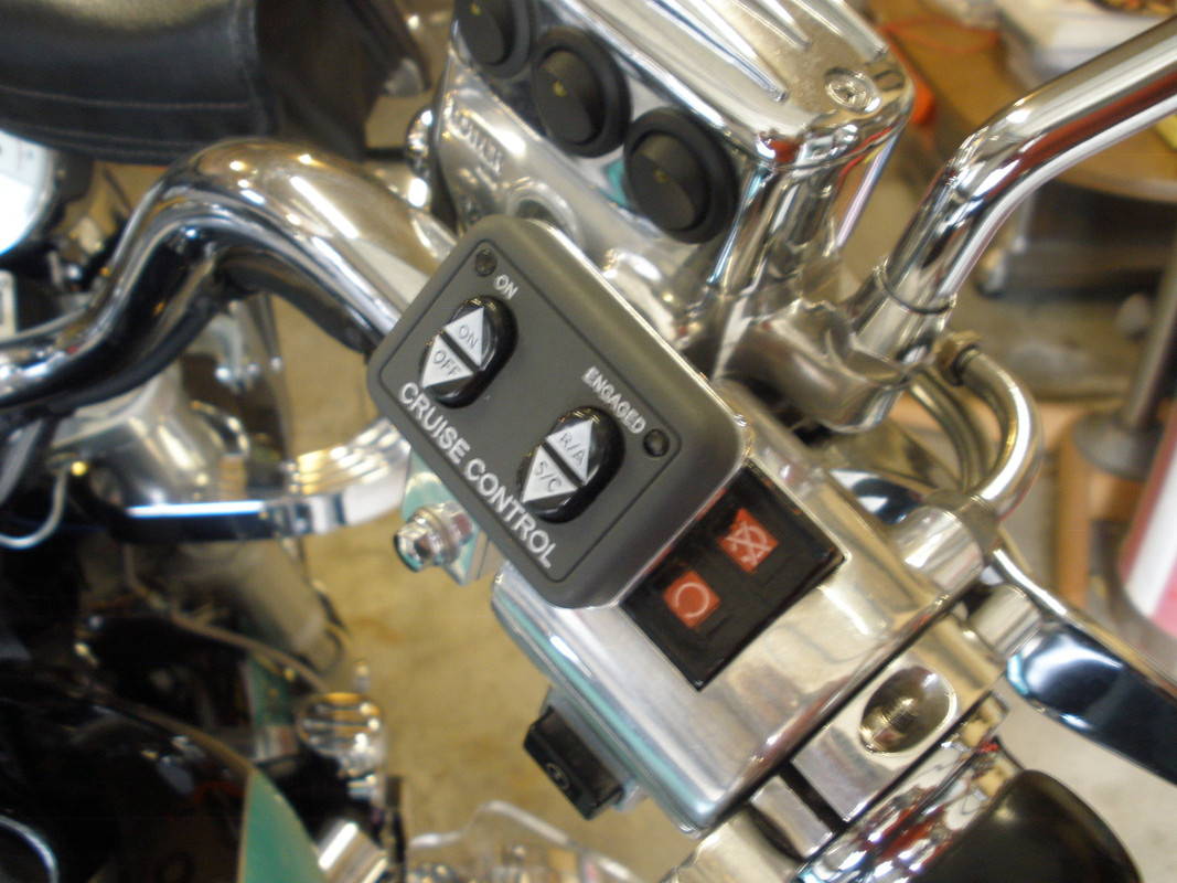
I have installed the Global Cruise in the compartment behind the battery, where I have always carried the OEM tools, a Leatherman, tire plugging stuff, and a miniature digital multimeter. I have had trouble giving up this space but there is always saddlebags. The Dash Mount Control is on the right handle bar within a thumbs reach of the throttle. The Speed Signal Generator (VSS) is on the rear wheel, hidden by the saddlebags.
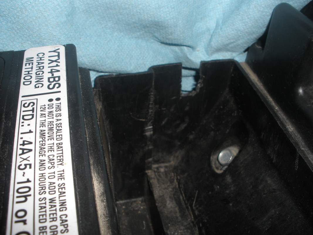
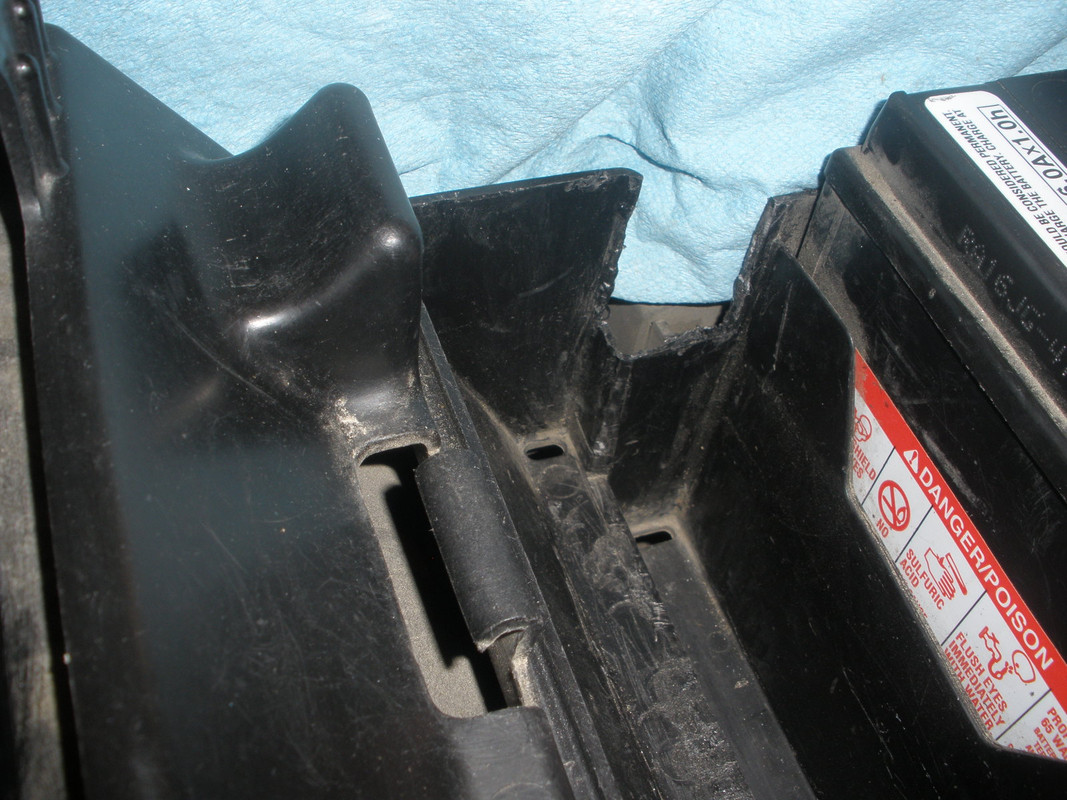
The Valkyries tool compartment was modified to accept the Global Cruise by first removing the divider in that space. That was actually done years ago to gain more usable room. Now, portions of each side were cut away to fit the Global Cruise and allow the servo control cable to exit on the right side. Below is the right side compartment cutout allowing the servo control cable to exit the compartment. The cutout is 1/2" wide and 7/8" deep.
Below is the left side tool compartment cutout which gives the Global Cruise the room it needs and provides a rest for that corner of the Global Cruise. The cutout is 1.5" deep.
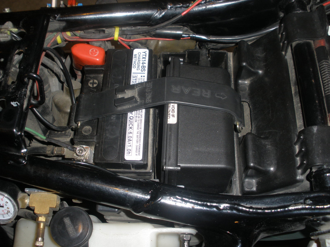
The Global Cruise is held in place by the OEM rubber strap that was used for the battery cover. The tight fit and the strap prevent any movement of the Global Cruise. The picture below is an early trial fit, perfect.
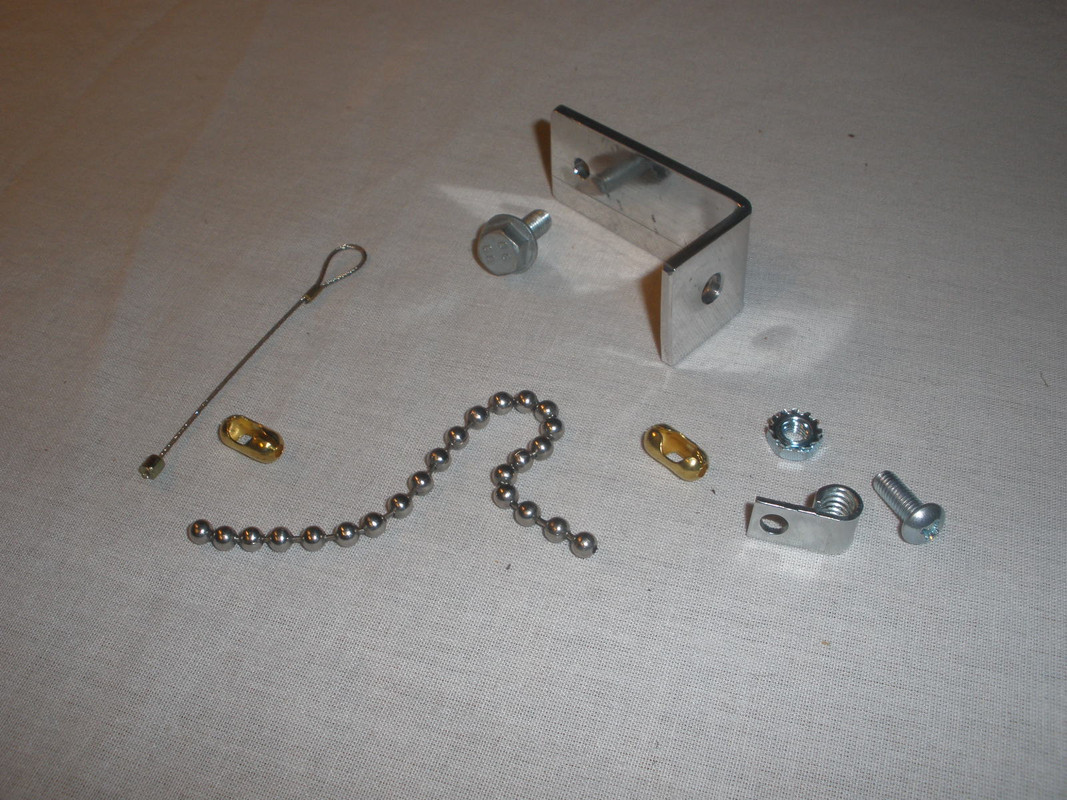
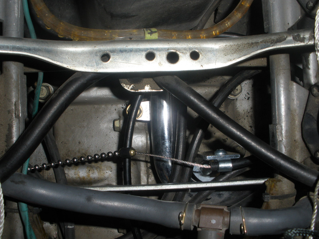
The servo control cable is routed forward, between the starter and the frame member just above the swing arm pivot, then above the engine where it passes under the throttle cross linkage and then makes a 270 degree clock wise loop where the end is secured just in front of the throttle cross linkage on an aluminum L-bracket attached to the engine using a screw originally used for the right reed valves. The picture below is the hardware used the secure the end of the servo control cable. The aluminum L-bracket is custom made and I no longer have its dimensions, but it was made to position the end of the servo control cable at the height of the throttle cross linkage and parallel to it.
The First thing to install is the loop cable (supplied) around the left end of the throttle cross linkage between carbs 4 and 6. The tiny cotter pin shown was a real pain to deal with, but it had to be removed and replaced.
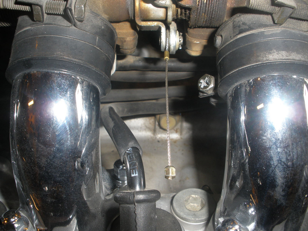
Then the aluminum L-bracket was mounted to the engine, the flag nut (supplied) was screwed on to the cable housing and then bolted on to the aluminum L-bracket.
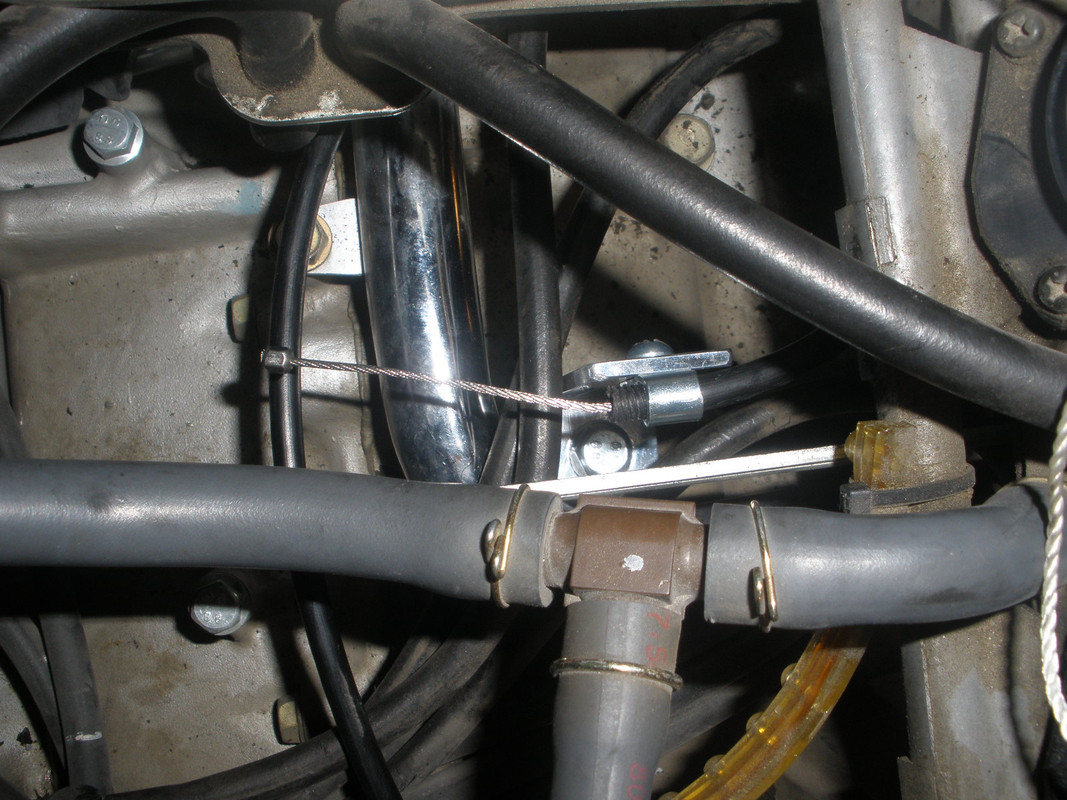
Back to the left side, the bead chain (supplied) was attached to the loop cable with a connector (supplied) and locked in place by crimping and using the connector cover (supplied). The bead chain allows the throttle to be moved when the cruise control is not enabled and even when enabled the throttle can be further manually opened. For my installation, I cut six beads off of the supplied chain to take up the slack.
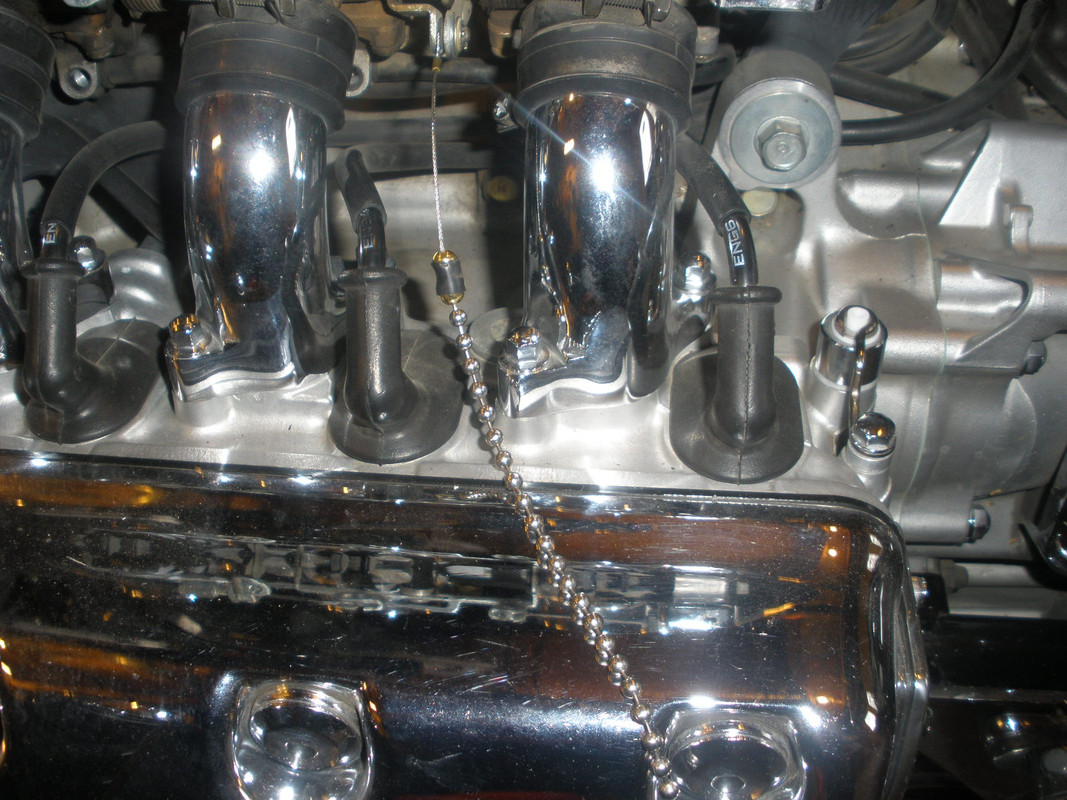
All that was left was to connect the other end of the bead chain to the end of the servo control cable as before, and lock it in place as before.
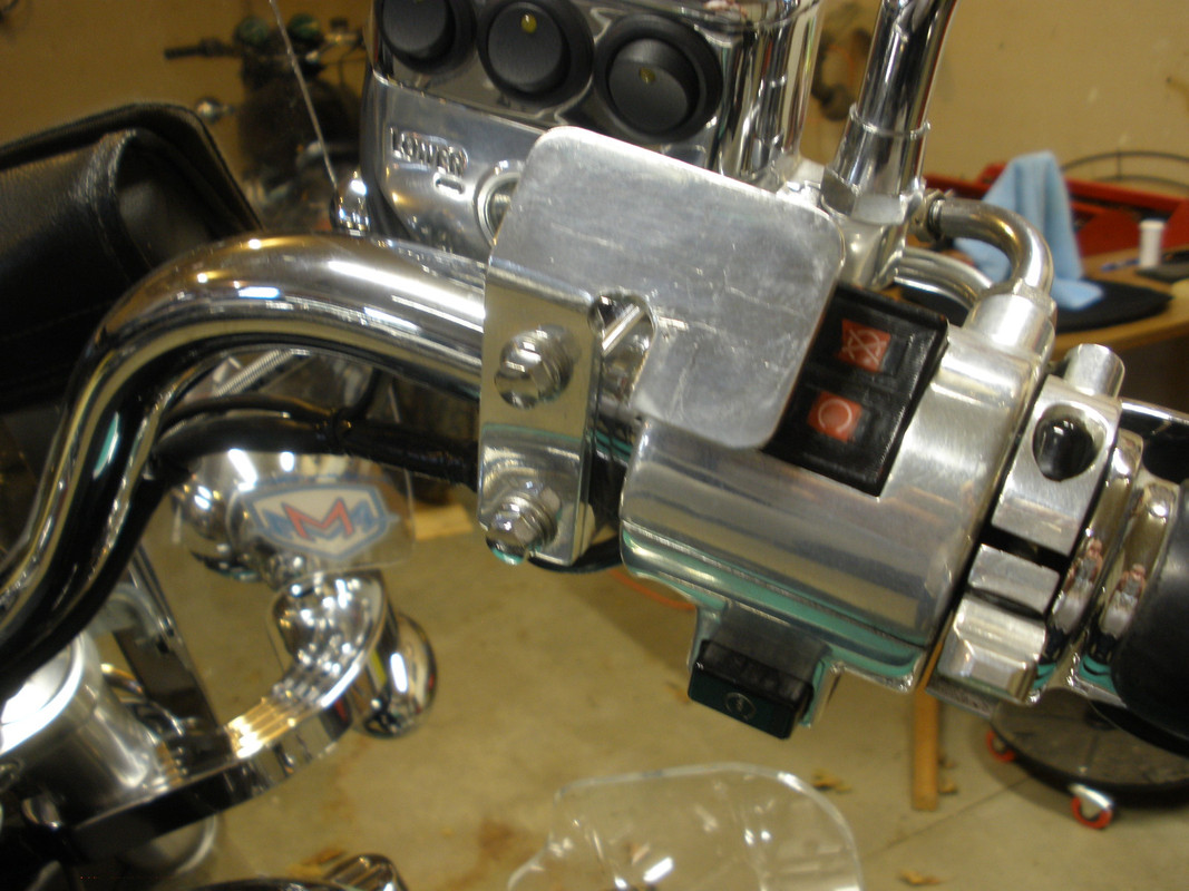
With the mechanical installation of the Global Cruise complete, I now turned to the Dash Mount Control. I made another custom aluminum bracket to hold the Dash Mount Control. It mounts to the front brake reservoir clamp and allows the control to cover about half of the engine kill switch. The wiring from the Dash Mount Control can pass out the back of the bracket and under the handle bar.
Ok now it was time to turn to that mess of wires that came with this project. The Rostra instructions provided little hint of the electrical function of each wire, only how they are typically installed in a truck or car. The wiring diagram in the instructions proved to be helpful, but it was very small.
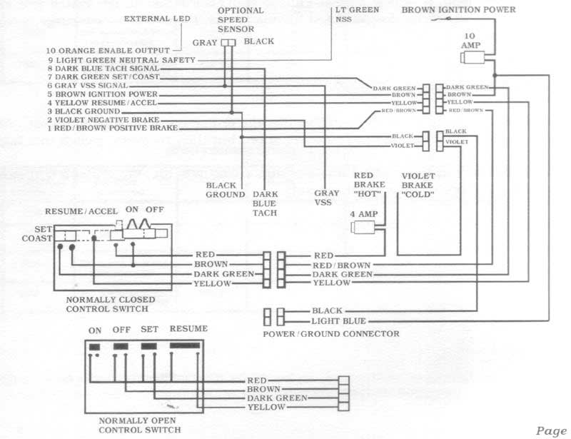
I tried to determine the function of each wire that terminates in the Global Cruise and the Dash Mount Control, determining where each wire will go and labeling it.
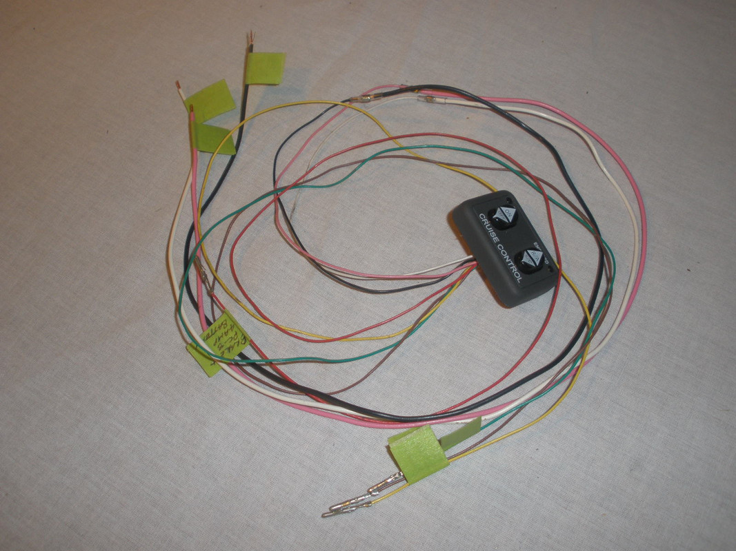
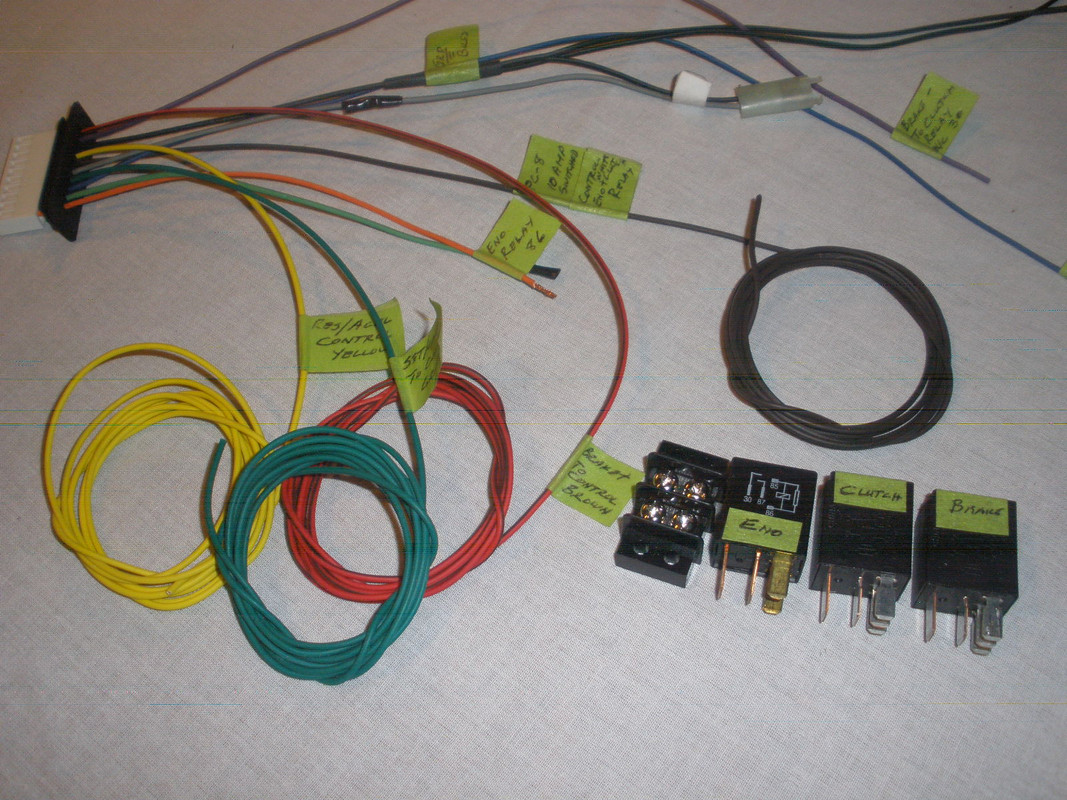
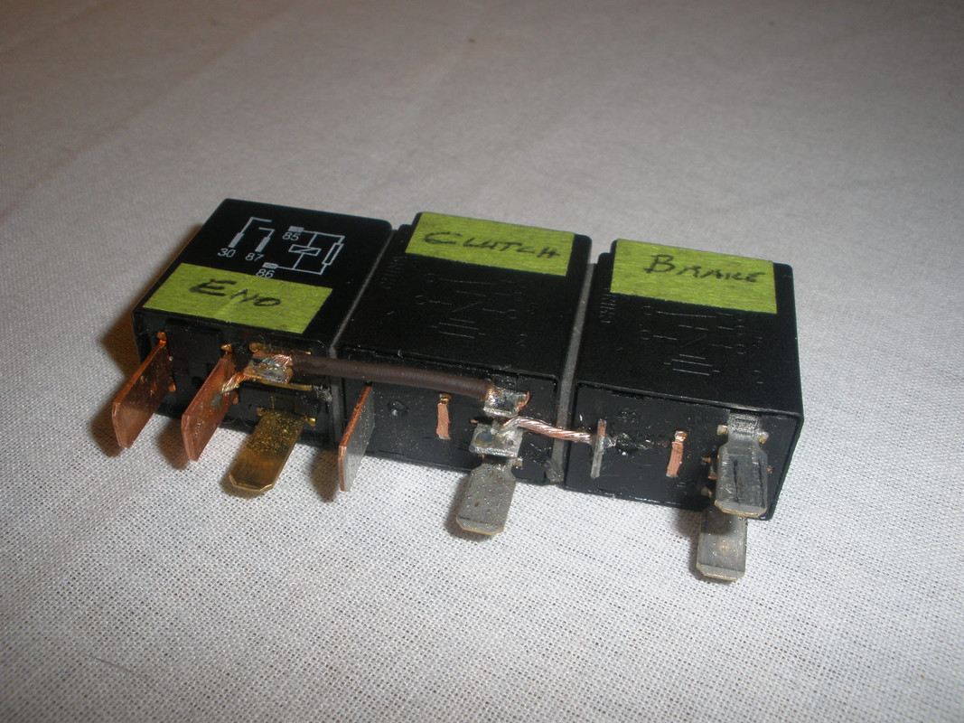
The other hardware in the above picture is a terminal strip which was attached to the Global Cruise and used as a local ground buss. In the end this ground buss had four wires to it. Also three automotive micro relays were used.
Since my brake lights are all LEDs, the cruise control would not sense enough resistance to disable the cruise when the brakes are applied. A T5 relay triggered by the brake is used to open contacts. The (green/yellow) brake wire is available in the connector just above the OEM fuse box. Likewise, I also wanted to disable the cruise when the clutch was pulled in. A second T5 relay is used to sense the Valkyries clutch interlock which grounds the (green/red) wire easily found at the starter relay.
The NC contacts of the brake and clutch relays are wired in series so whenever either control is pulled, the cruise control will disable. A third T4 relay was required because the 3592 Dash Mount Control's Engaged Light required 12+ volts on its pink wire while the servo unit only put out ground to the orange wire when the cruise control was engaged. That was explained in the instructions for the Dash Mount Control.
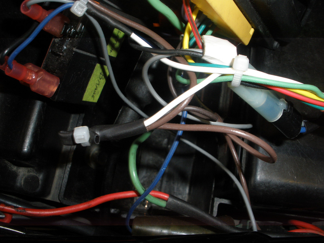
I cut out all the fuses and connectors from the Rostra harness except for the Auxiliary Speed Sensor Connector, a two prong connector that is used to plug in the Speed Signal Generator. I always choose to solder and shrink wrap wire connections where I can.
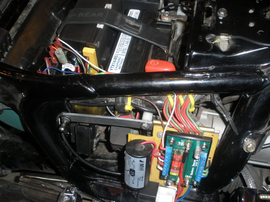
I had installed an Eastern Beaver PC-8 fuse/ground box many years ago to power all of the electrical accessories added by previous owners and myself. I just refer to it as the "PC-8". Here are wire runs for the wires leaving the Dash Mount Control.
Dash Mount Control Destination
============= ===========
Red (Brake+) --------------------------------- PC-8 +12V 4 AMP Switched
Brown (Brake active +) ---------------------- Global Cruise - Red/Brown
Yellow (Resume/Accel) ----------------------- Global Cruise - Yellow
Dark Green (Set/Coast) ---------------------- Global Cruise - Dark Green
Black (Ground) -------------------------------- Global Cruise - Ground Buss
White (Ignition +12V) ------------------------ Sealed Power Connection
Gray [#1] (Back Light +) to White ---------- White (on circuit board)
Pink (Engaged Light, +12V req'd ) ---------- Eno Relay - contact 30
Blue [#1] (Back Light ground) to Black ----- Black (on circuit board)
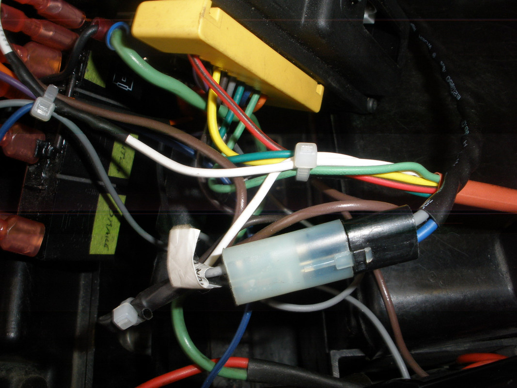
[#1] The Grey and Blue wires never leave the Dash Mount Control because they are jumpered to the White and Black respectively right on the small circuit board within the Dash Mount Control. See the picture below.
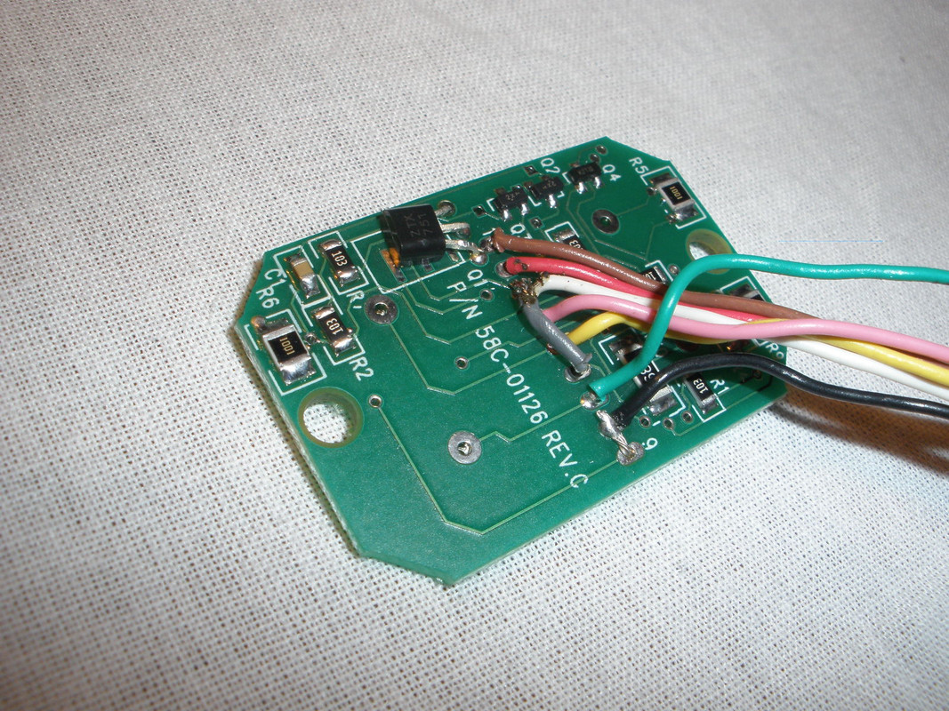
All the wires from the Dash Mount Control are routed under the right handlebar into the right side of the frame and lead back to the battery location following the OEM wiring paths.
Now we will turn to those three relays that I require. Here are wire runs for the wires between the relays and those going to other devices.
Relay Connections
===============
ENO Relay - coil 85 [#2] ----------- ENO Relay - contact 87
ENO Relay - coil 86 ----------------- Global Cruise - Orange
ENO Relay - contact 30 ------------- Dash Mount Control - Pink
ENO Relay - contact 87 ------------- Sealed Power Connection
Clutch Relay - coil 85 [#2] --------- ENO Relay - coil 85
Clutch Relay - coil 86 --------------- Valkyrie - Green/Red
Clutch Relay - contact 30 ---------- Global Cruise - Violet
Clutch Relay - contact 87A --------- Brake Relay - contact 30 [#2]
Brake Relay - coil 85 ---------------- Valkyrie - Green/Yellow
Brake Relay - coil 86 ---------------- Ground Buss
Brake Relay - contact 30 [#2] ------ Clutch Relay - contact 87A
Brake Relay - contact 87A [#2] ----- Brake Relay - coil 86
[#2] These four connections comprise the shortest possible jumpers on the relays as shown below.
I assembled the three relays together in a pack, removing unused spade tabs and soldering the four [#2] connections together. These connections were then insulated by painting on a sealant.
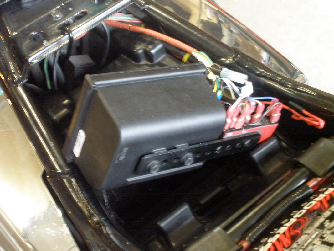
It is important to have enough wire length to remove the Global Cruise from its compartment to allow access to the dip switches which now face to the front of the Valkyrie. The mounting bracket for the Global Cruise (supplied) was cut down and attached with the screws (supplied). That added a stable support for the Global Cruise within the compartment and provided an attachment surface for the relay pack. It was convenient to keep all this together, cutting down on the maze of wiring.
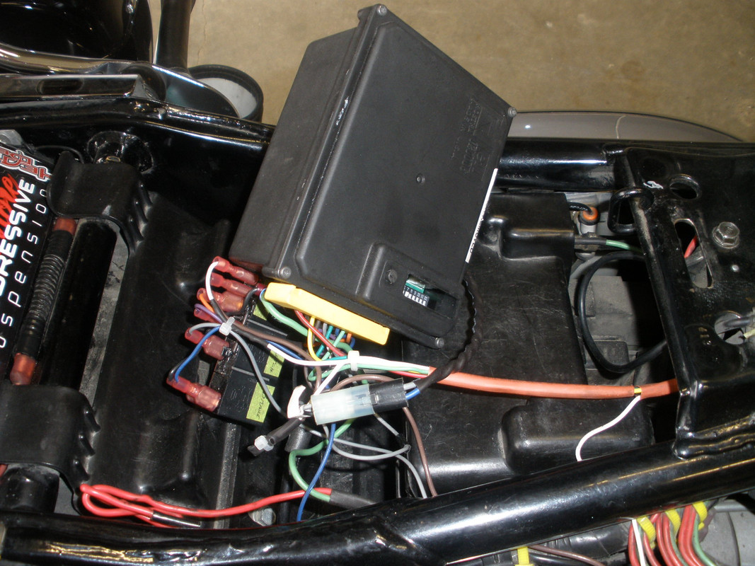
From the Global Cruise unit point of view, here are wire runs for the wires leaving the unit.
Global Cruise Destination
======== ===========
Red/Brown (Brake +) -------------- Dash Mount Control - Brown
Violet (Brake -) --------------------- Clutch Relay - contact 30
Black (Ground) --------------------- Ground Buss
Yellow (Resume/Accel) ------------- Dash Mount Control - Yellow
Brown (Accessory Power) ---------- Sealed Power Connection
Grey (VSS) -------------------------- Auxiliary Speed Sensor Connector (the other leg is trimmed back)
Dark Green (Set/Coast) ------------ Dash Mount Control - Dark Green
Dark Blue (Tach) ------------------- Ground Buss
Light Green (NSS) not used.
Orange ------------------------------ ENO Relay - coil 86
Note the location of the window into the dip switches.
The local Ground Buss terminal was mounted on the end of the Global Cruise. Is has the following connections.
Ground Buss Destination
======== ===========
Black ------------------ Dash Mount Control
Black ------------------ Brake Relay - coil 86
Dark Blue ------------- Global Cruise - Dark Blue
Green ----------------- PC-8 Ground Buss
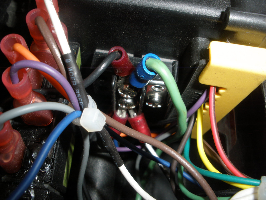
Four +12V Switched wires come together to supply power to the Global Cruise, Dash Mount Control and Relay Pack.
Sealed Power Connection
================
Brown ------------------------- PC-8 +12V 10 AMP Switched
Brown ------------------------- Global Cruise - Brown
Brown ------------------------- ENO Relay - contact 87
White ------------------------- Dash Mount Control - White
I slightly messed up the wiring that was installed when the PC-8 went in, but so be it. Here you see what the Eastern Beaver PC-8 looks like with the cover off. For this Rostra installation, from the top, the second 10 AMP fuse and the 4 AMP fuse was added. I still have room for one more switched circuit. What will it be?
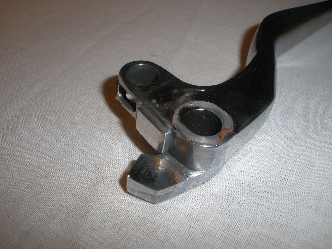
The Valkyries clutch interlock is actuated by a micro-switch below the clutch reservoir body, but that switch was tripped only when my clutch lever was actually touching the grip, well after the clutch was disengaged. There has been times when the switch could not be tripped and thus the Valkyrie not started while in gear. When this was now also used to disengage the cruise control, I needed the switch to be tripped as the clutch was disengaging. The solution was to modify the clutch lever, adding a small pad to trip the micro-switch earlier in the throw of the clutch lever, while not damaging the plastic micro-switch.
The aluminum pad is J-B Welded to the clutch lever as shown below.
The last item to install is the Vehicle Speed Sensor (VSS). On a Valkyrie Interstate, that can be tapped off the electronic speedometer. However the Valkyrie Standard and Tourer have a mechanical speedometer. I used the Speed Signal Generator from Rostra to provide the required pulsed signals to the Global Cruise.
While the location of the Speed Signal Generator is out of the way and hidden by saddle bags, it had a down side. To remove the rear wheel, one must first remove the bracket that holds the pickup coil. This can be done by loosing the axial nut, removing the pin which locks the caliper mounting bracket, rotating that bracket and unscrewing my aluminum bracket.
I realized this after I was well into the installation, but I found no better alternative location for the Speed Signal Generator.
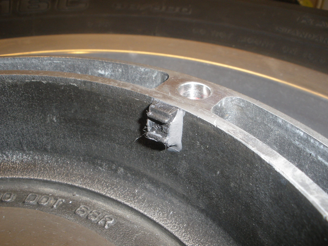
Nine of the magnets (supplied) were J-B Welded to the left inner hub of the rear wheel, just inside the brake disk. Originally, I only used three magnets but that was at the low end of the Global Cruise's VSS operating range. More magnets (pulses/mile) may allow the Global Cruise to operate more smoothly. Nine magnets with my wheel circumference produce 6912 pulses/mile (PPM).
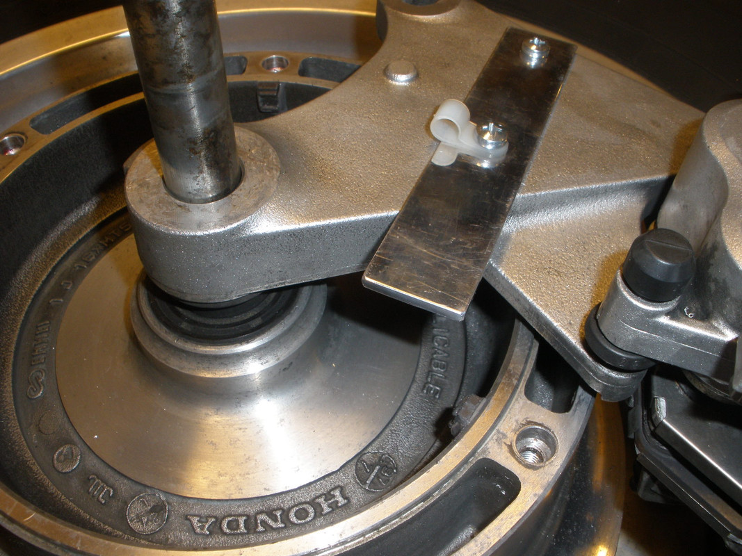
I then had to make an aluminum bracket that would locate the pickup coil close to the magnets. The geometry got complex so it had to be made in two pieces. The first was a flat strap that screws into the rear brake rear brake caliper mounting bracket. Holes were drilled and tapped in the bracket to accomplish this.
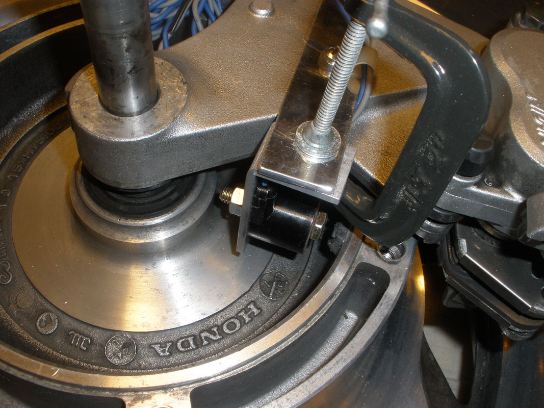
I then made an aluminum L-bracket and bolted the pickup coil to it. In the picture below we are getting the proper alignment of the pickup coil to the magnets.
After securing the two pieces of the bracket together with pop rivets and cleaning things up we get this. The grey and blue wire pair are routed along the top of the swing arm and then up to the Global Cruise. I installed a set of spade connectors along the swing arm so the VSS assembly may be completely removed. That is now required to remove the rear wheel.
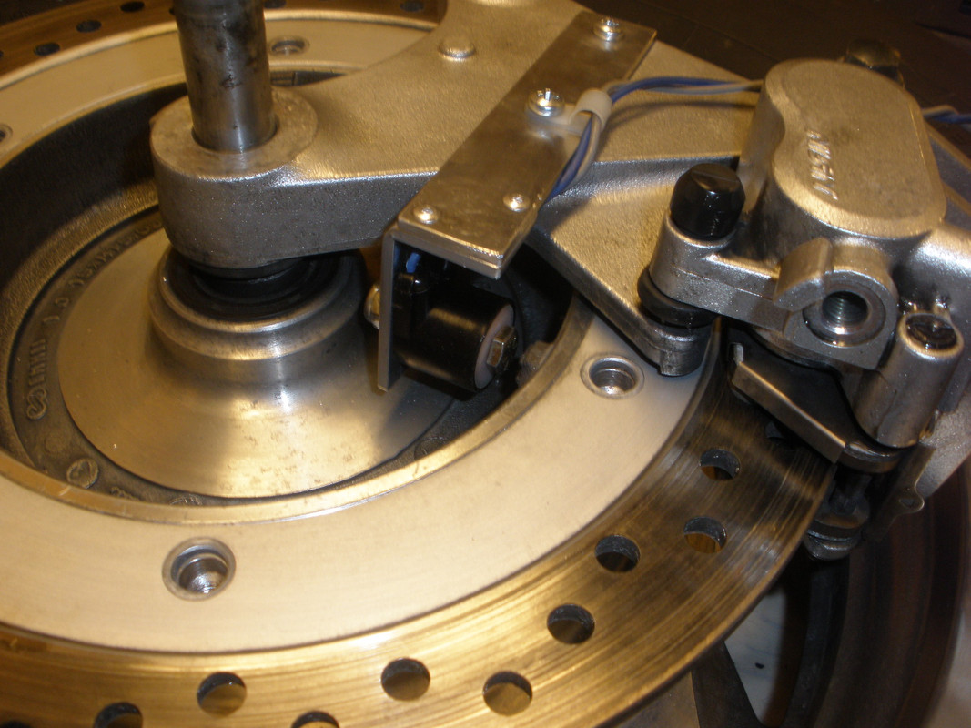
The grey and blue wire pair are routed along the top of the swing arm and then up to the Global Cruise. I installed a set of spade connectors along the swing arm so the VSS assembly may be completely removed. The grey and blue wire pair are plugged into the Global Cruise with the Auxiliary Speed Sensor Connector.
Speed Signal Generator Destination
=============== ===========
Grey -------------------------- Global Cruise - Grey
Blue -------------------------- Global Cruise - Black
The rear half the battery box cover was removed so as to only cover the battery. Here is what the final installation looks like.
The Dash Mount Control is secured to its mounting bracket with 3M Automotive Trim Tape after it was sealed up with silicone. This control has a membrane on the front surface but was not designed for outside use.
Tuning in the Global Cruise is required to get it in tune with the vehicle in which it is installed. There should be no more than 1/8" slack in the bead chain at the end of the servo control cable. Hopefully we got that right because we can no longer get to it without a lot of work. I was concerned about the amount of travel that the throttle cross linkage has vs. that of a typical
car's throttle body. The Valkyrie has only 7/8" from idle to wide open, where a car typically has over twice that amount. Hopefully the Global Cruise is sensitive enough to not surge in the throttle adjustments.
Now the Global Cruise dip-switch's are set with #4 and #8 on, all other are off. Switch #4 indicates that the VSS pulse rate is at least 6000 PPM. Switch #8, is for the Engine/Setup Timer. I determined this after several runs on a hilly road, trying various other switch settings. This seemed to work the best.
A couple of weeks ago, I managed to get the Valk out on I-90, making a run to Austin, 30 miles away. The Rostra operated fairly well but did have some quirks relating to sensitivity that I could probably live with but will try to eliminate. I thought one problem might be the amount of play in the beaded chain that pulls the throttle open. But, after a close look, there appears to be little sag in it when the power of off. I decided to ease my concern that the Global Cruise was operating at the extreme end of its VSS range with only three magnets installed on the rear wheel, so I tripled them, requiring another $52 investment in the pack of ten magnets. I got the additional six magnets installed a few days ago and had to turn on switch #4.
Yesterday, I make run to Owatonna and Blooming Prairie to test out the latest change. I believe the additional PPM improved the smoothness of the control, but that was only my impression. I would hate to think that I pored the additional money down the drain.
Note that, over time, I have been making some alterations to the Rostra 250 installation and that may continue. I will continue to document these changes to my VRCC Brothers and Sisters by making alterations to this original post and also appending another post on this thread.
Readers only have to read this original post to see exactly what was done...


