Valkyrie Riders Cruiser Club
June 28, 2025, 07:37:39 AM *
Welcome, Guest. Please login or register.

Login with username, password and session length
Ultimate Seats Link VRCC Store
Homepage : Photostash : JustPics : Shoptalk : Old Tech Archive : Classifieds : Contact Staff
News: If you're new to this message board, read THIS!
 
MarkT Exhaust
Pages: [1]   Go Down
Send this topic Print
Author Topic: PC8 Install and Electrical Layout  (Read 1537 times)
Bigwolf
Member
*****
Posts: 1501


Cookeville, TN


« on: April 05, 2018, 12:30:32 PM »

PC8 Install and Layout

Hey Folks,
When I bought my ‘98 Standard, it already had some electrical add ons and I had more in mind but I do not like electrical octapuses.  From the tangled clutter of wires and fuse holders to a little less tangled cluster of wires and a more organized electrical center for fuses and relays.  I saw a photo several years ago of a hinged panel under the right side cover.  I liked the idea.  What follows is my solution:

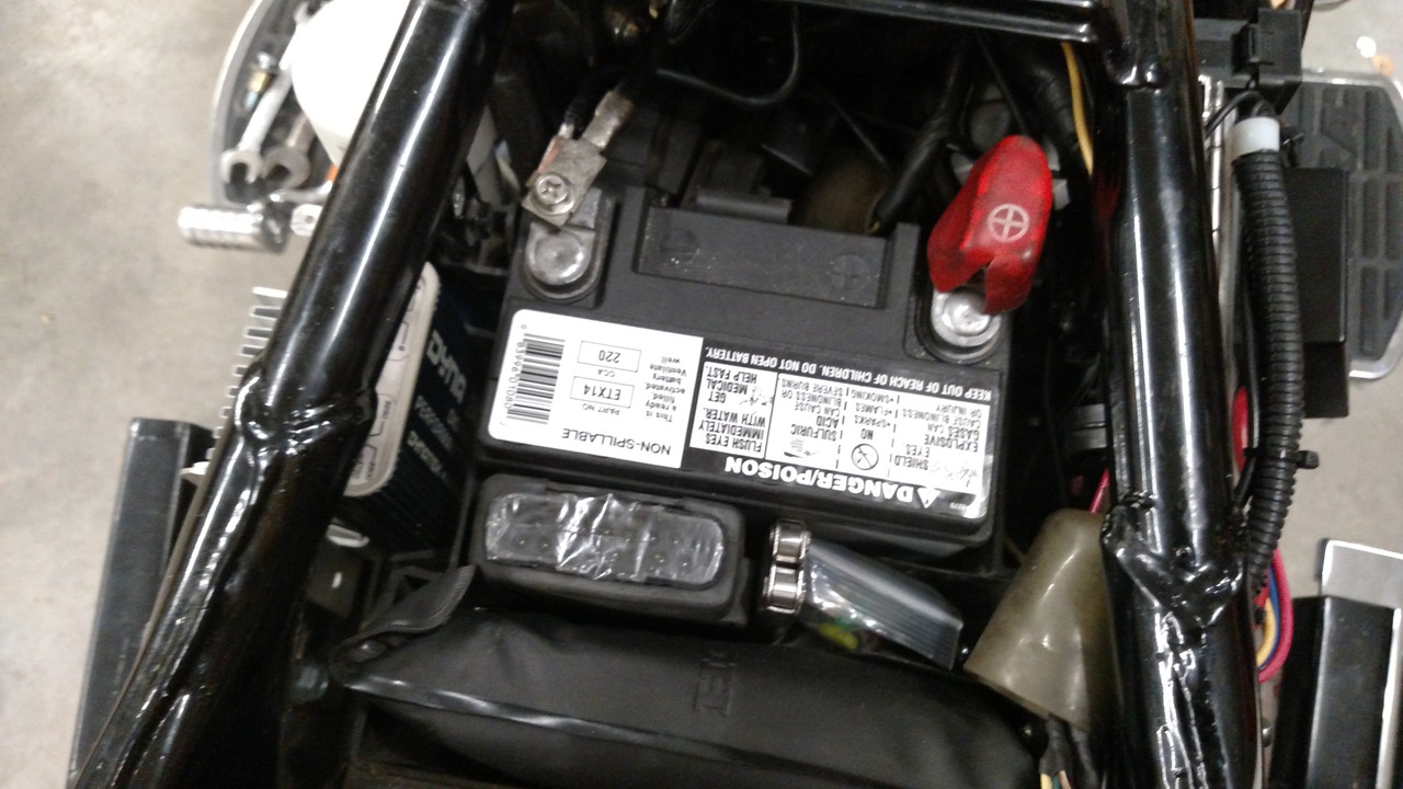
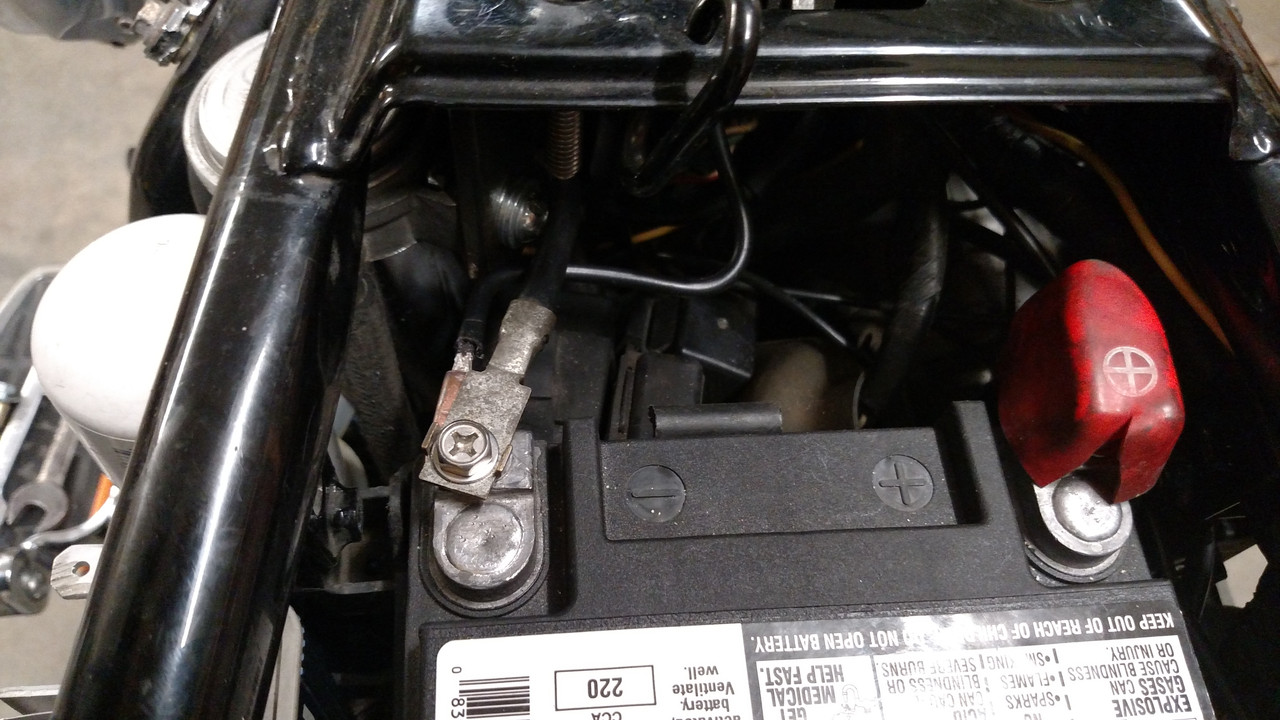
What I had under the seat and battery cover:


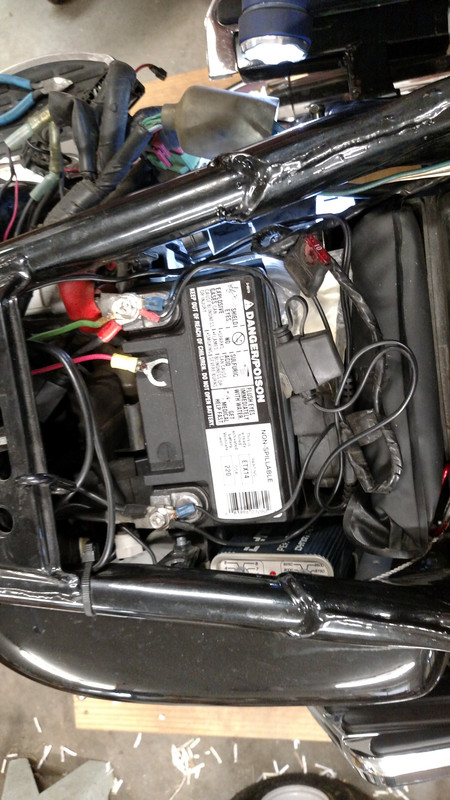
Under the side cover:


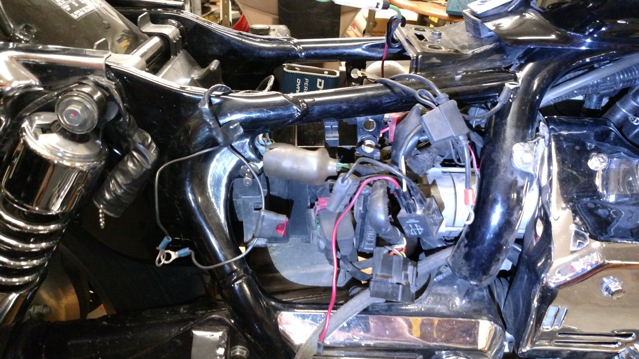
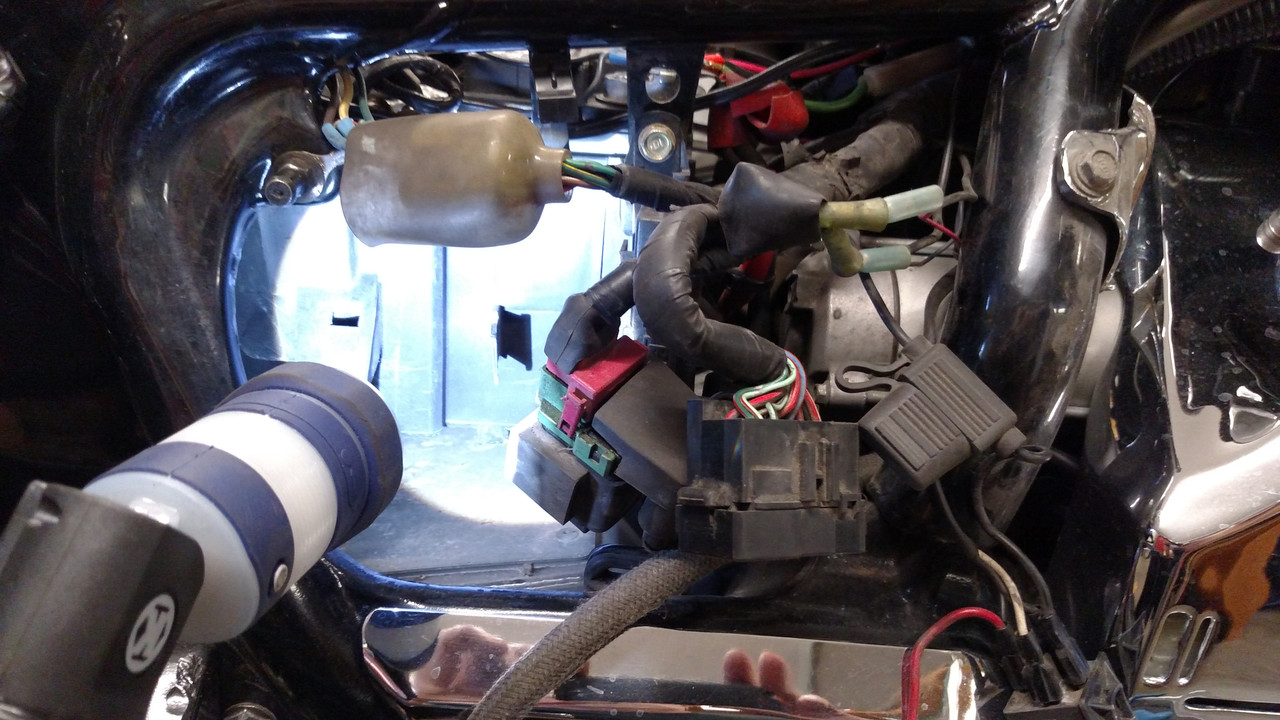
I pulled some stuff out and shined a bit of light in there to see how I could arrange things.


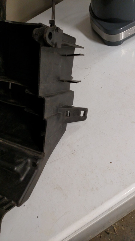
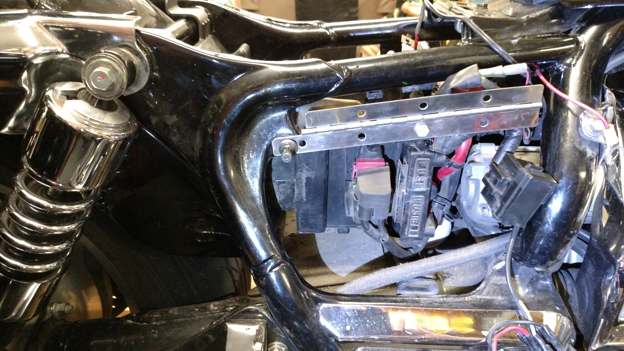
  Pulled the battery box and cut off the tab that held the OEM fuse block. Not the ones in the top of the photo, but the one with the 2 square holes.  I decided I would move that OEM fuse panel so would not be using that long tab you see on the side of the box.


I bought a 12 inch piece of stainless piano hinge at the hardware store and trimmed it to fit my application.  I put a long bolt thru one of the hinges original holes and used a spacer to hold the hinge out for clearance.  This bolt replaces the battery box mounting bolt on this side.  The left side of the hinge is held by the side panel catch post.  I had to cut a little more off the right side of the hinge after this photo to make room for the OEM fuse panel.


In this photo you can see the OEM fuse panel attached to the right side of the hinge.  I used a very short piece of aluminum angle to form this attachment point.


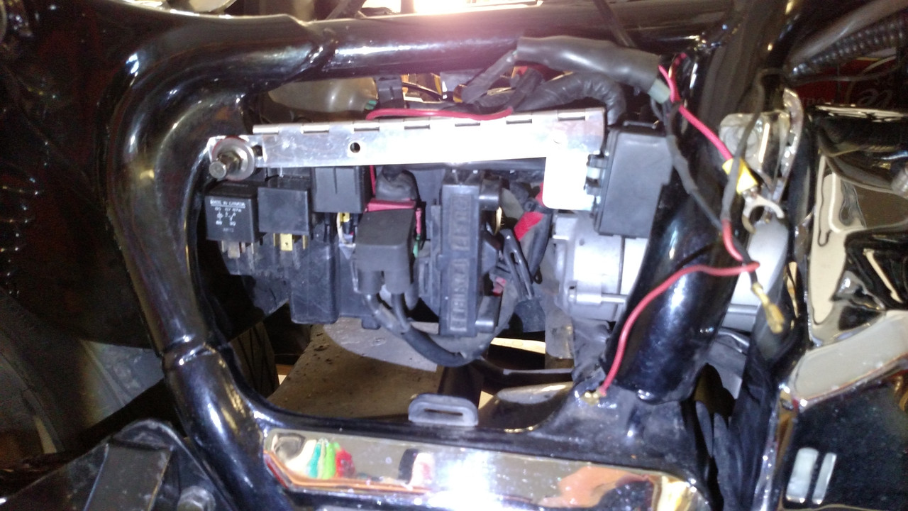
In this photo, you can see 3 of my relays mounted on the side of the battery box.  I don’t remember exactly right now but I am thinking 5 more went in that area by the time I was done.


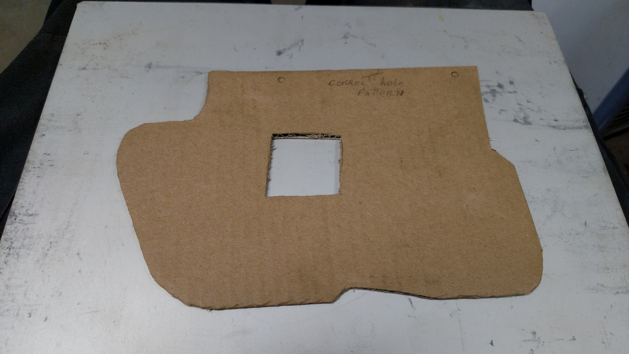
Now the fun part!  I took a piece of cardboard and cut and trimmed it until I had the shape I wanted for the hinged panel.  I marked for the mounting holes using the existing holes in the hinge.  Also, since my panel was going to be aluminum, I cut a window in the panel around the top of the starter relay.  I probably don’t need that window since it would be very difficult for the panel to get hit hard enough to short out the start relay but I did it just for insurance against such ugliness. 


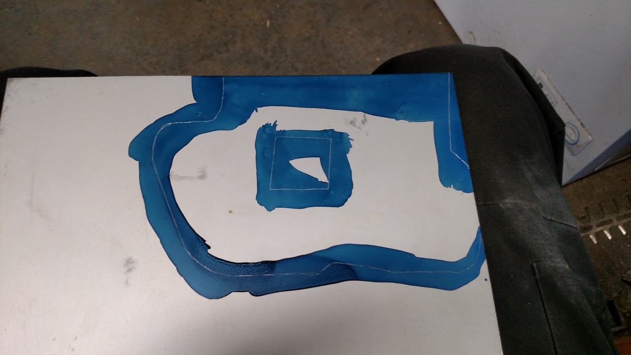
Transfered the pattern to the aluminum.


After cutting the panel out, I drilled and tapped the mounting holes so that I could use button head screws from the inside of the hinge out thru the panel leaving enough bolt sticking out to use a nut on for wire clamps.


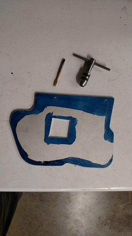
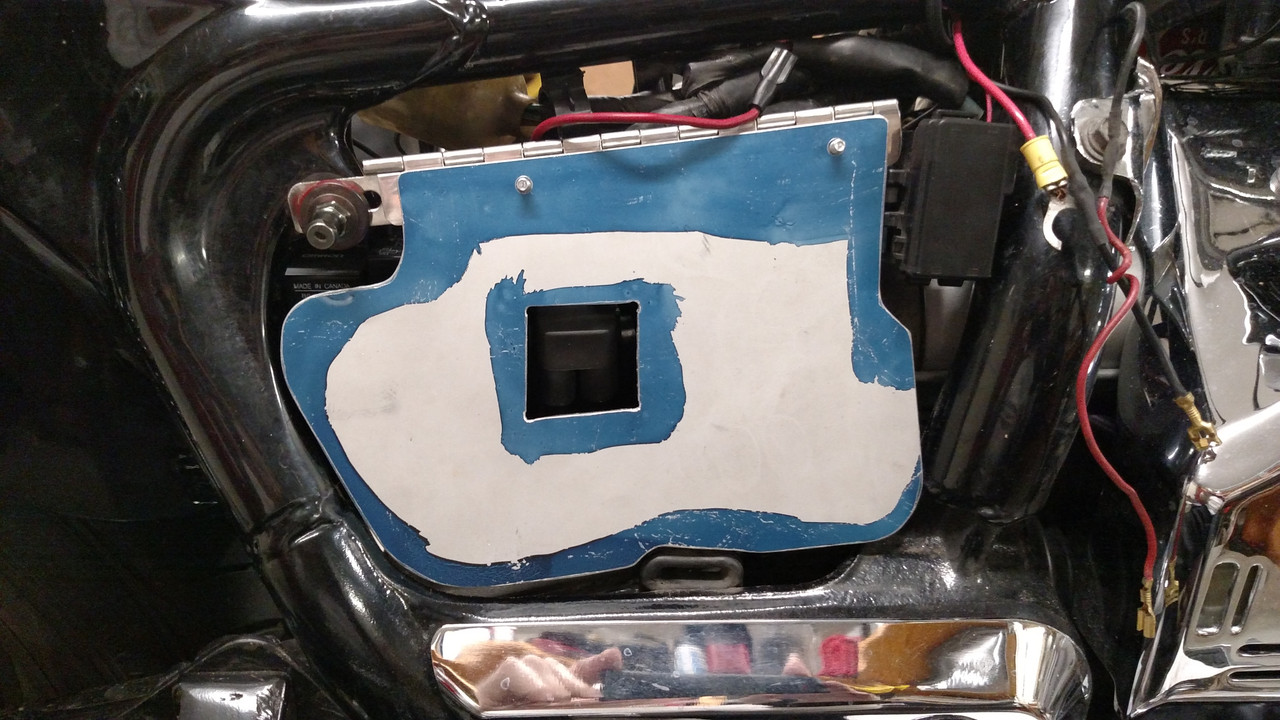
Panel bolted to the hinge and with a bit of final trimming and filing fitting nicely.  Note; the bottom right corner of the panel hits against the frame when closed.  This is the stop that keeps the panel from being pushed in to far.


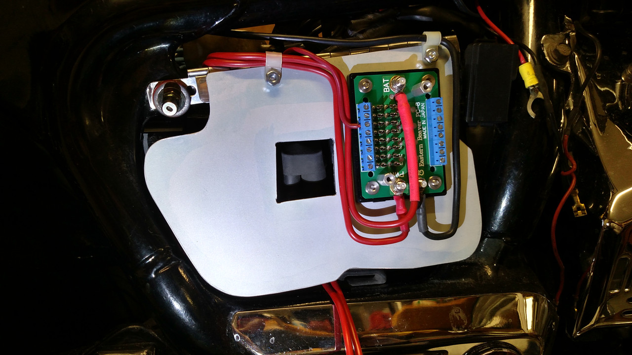
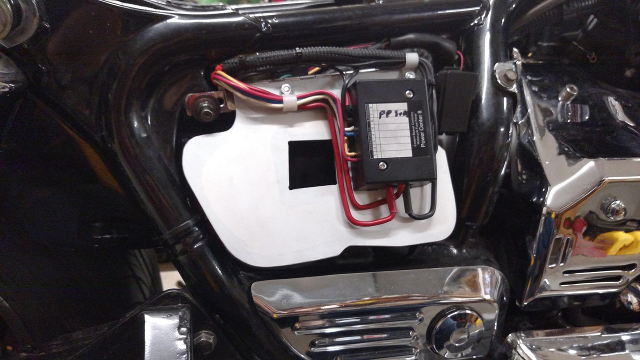
Finally had the PC8 mounted and began the task of wiring.  Both main hot circuits are fused and one is on all the time while the other is on only with the key on.


I bought these pig tails for relays but did not want splices everywhere so pulled the wires out.  I soldered brass connectors (from Digikey) to the correct length of wire for each circuit I was making.  These new connectors just snap right into the black plastic housing so good plug and no splices.


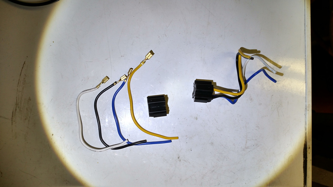
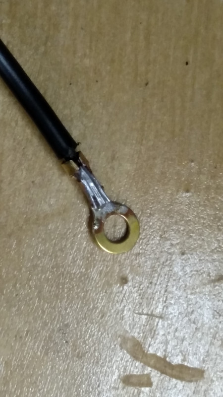
A crimped terminal is an electrical problem just waiting for the most inopportune time to fail.  So....I solder them all.


The finished panel and a look inside the battery box after this loving exercise was completed.


I also added a short pigtail under the seat to be able to plug in for lights on a trailer.  Never thought I would use that but..........I have.  Hmmmm.....I had a photo of that too but don’t have it uploaded now.  Maybe later.

Hope this is helpful to some.

Bigwolf
« Last Edit: April 16, 2018, 09:36:49 AM by Bigwolf » Logged
hubcapsc
Member
*****
Posts: 16779


upstate

South Carolina


« Reply #1 on: April 05, 2018, 01:11:10 PM »


Your work seems neat and untangled  cooldude ...

My crimped connections haven't failed yet, but I did get a
failure on a wire I added without a loom...


-Mike "that's Gordon, not the loom..."
Logged

Bigwolf
Member
*****
Posts: 1501


Cookeville, TN


« Reply #2 on: April 05, 2018, 01:32:44 PM »


Your work seems neat and untangled  cooldude ...

My crimped connections haven't failed yet, but I did get a
failure on a wire I added without a loom...


-Mike "that's Gordon, not the loom..."

I remember that......well, not the wire failure but I remember Gordon working on your bike at the Veterans ride.  In  fact I am in that photo.

I noticed in the photo of my finished power panel that the plastic conduit was not on the power wires, only on the ground wires.  I do have a nice red plastic conduit over the power wires but obviously I did not have it on there when I took that photo.  It would not be good to have those power wires vibrating against the top of that hinge with nothing to protect them.  Even that plastic conduit, or loom, should be checked periodically to be sure it is not worn.

Bigwolf
« Last Edit: April 05, 2018, 09:47:04 PM by Bigwolf » Logged
Jess from VA
Member
*****
Posts: 30407


No VA


« Reply #3 on: April 05, 2018, 01:33:36 PM »

A really ingenious and nicely done project BW.  cooldude  And a great post/pics about it too.  Thank you.

I don't know about We..... but I am not worthy.  (I still have about 7 wires to pos. terminal on one bike.)

https://www.youtube.com/watch?v=-FucbvoFFy0
« Last Edit: April 05, 2018, 01:37:17 PM by Jess from VA » Logged
bill-jr
Member
*****
Posts: 1034


VRCC # 35094

murfreesboro


« Reply #4 on: April 05, 2018, 05:10:25 PM »

Great looking . . .
job well done there . . .
Im not patient enough for that .....
Logged

Ever danced with the devil In the pale moon light ?
99' Black tourer
The emperor has no clothes
Member
*****
Posts: 29945


« Reply #5 on: April 05, 2018, 05:20:40 PM »

You did an excellent job  cooldude Thanks for showing us. Wanna do about 40 bikes in Roanoke ?  2funny
Logged
Motodad71
Member
*****
Posts: 150


Westerville OH


« Reply #6 on: April 05, 2018, 05:30:58 PM »

Awesome solution and write up, you have me wanting to do something similar.
Logged

1997 yellow/black Valkyrie standard "Thor"
John Schmidt
Member
*****
Posts: 15210


a/k/a Stuffy. '99 I/S Valk Roadsmith Trike

De Pere, WI (Green Bay)


« Reply #7 on: April 05, 2018, 05:31:24 PM »

I'd show you my rendition of extra stuff wired in but would be too embarrassed. To give you an idea....think of a bowl of spaghetti dropped on the floor.  Grin Embarrassed

Really nice job on the panel, looks like you moved the start relay along with other stuff.  cooldude  I'd like to do something like that but afraid it would take me away from screwing something else up on my old bike, or bicycle, air compressor hook up, installing outside garage door opener.....see, I have plenty of places/projects for me to ruin.  2funny
Logged

MarkT
Member
*****
Posts: 5196


VRCC #437 "Form follows Function"

Colorado Front Range - elevation 2.005 km


WWW
« Reply #8 on: April 05, 2018, 06:44:37 PM »

Nicely done, Bigwolf.  Cleaning up a rat's nest is worthwhile and makes maintenance and esp needed repairs on the road go much easier.  That was a big goal for me when I set up Jade after making a mess of all the options added one at a time on Deerslayer.  Jade doesn't look as neat as yours but it's a lot more complex with 17 relays.  I did use the PC-8 under the right cover but didn't design in a nice flip-up panel like yours.  Good idea.  I did put the majority of the relays on a pull-out panel behind the battery and worked to loom the wires as much as possible.  Maintenance goes pretty easy for me now!  +1 on the soldering everything - absolutely!

« Last Edit: April 05, 2018, 06:47:15 PM by MarkT » Logged


Vietnam-474 TFW Takhli 9-12/72 Linebckr II;307 SBW U-Tapao 05/73-4
Motodad71
Member
*****
Posts: 150


Westerville OH


« Reply #9 on: April 05, 2018, 08:31:41 PM »

Why all the relays if you have a PC8?
Logged

1997 yellow/black Valkyrie standard "Thor"
Bigwolf
Member
*****
Posts: 1501


Cookeville, TN


« Reply #10 on: April 05, 2018, 10:04:24 PM »

I want to thank everyone that has complemented my work.  It is always nice to hear and it has made my effort to get it all posted worthwhile.

You did an excellent job  cooldude Thanks for showing us. Wanna do about 40 bikes in Roanoke ?  2funny

Well, ..... I had not thought about that.  I might be willing to do something toward that end though.  I guess, if someone was serious about having that setup and they had a PC8 they wanted installed, they could send a message to me.

Bigwolf

Logged
Brian
Member
*****
Posts: 996


Monroe, NC


« Reply #11 on: April 06, 2018, 02:45:43 AM »

Awesome job Bigwolf. Your first picture is kinda what I have going on. The PC-8 is my future project. The hinge is an awesome way to go. Do you have something there to hold that panel up and out of the way?
Logged
JC19
Member
*****
Posts: 51


Rush City, Minnesota


« Reply #12 on: April 06, 2018, 06:09:03 AM »

Very nice work. It always amazes me how clean a bike looks that doesn't have two miles of dirt road to travel on every time I go out.
Logged
MarkT
Member
*****
Posts: 5196


VRCC #437 "Form follows Function"

Colorado Front Range - elevation 2.005 km


WWW
« Reply #13 on: April 07, 2018, 08:26:30 AM »

Why all the relays if you have a PC8?


Actually almost all of the circuits I added have their own relays - don't need switching at the PC-8.  The latter provides most of the fuse functions only, in a neat way. Though there are a few more inline fuses as well as the OEM fuse box, mostly right nearby.  The circuits have specific needs - a general "switch it on with ignition" function at the PC-8 doesn't fit many of the circuit's requirements.

They have different functions and different triggers.  Some are wired as latch relays. Usually each new accessory has it's own relay - some more than one depending on circuit requirement. The "spots" which are actually H4 headlights, have 4; the rear brake/turns have 2, the fuel system 3 IIRC.  Here's the spots headlight circuit, for example. Note, I could have done this with 3 relays - power the parking bulbs off of R3 pin 87a if R3's pin 30 power was from "select switch" instead of 12v.


My turn signal circuit provides run-brake-turn functions from the rear marker lights.  I've used this circuit on Deerslayer and Jade.  These relays are used in a different way from relay's normal use - use the trigger (the running light circuits in front) to select which wire powers the bright filiment - brake or turn signal.  Simple, inexpensive, dead reliable and requires an afternoon to install with basic wiring skills.


All of the relays in my circuits are automotive electromagnet relays, not solid state as I've used them for years and have high confidence in them.  However, they can and do fail.  Generally the cheap ones that are packaged with accessories don't hold up at all - I toss them immediately and get quality ones from auto stores (or the same online). I keep a couple of them in my bike parts kit; might have to replace one of the 17 on the bike every couple years or so. I have not tried to use digital relays - MOSFETs - as I haven't researched or experimented on their compatibility with 12v automotive circuits.  I suspect they likely aren't compatible. Might work with appropriate tweaks to the circuit but I want to keep it simple. They are used extensively in other applications, appliances, computer circuits and so on. Reliable.
« Last Edit: April 07, 2018, 11:08:46 AM by MarkT » Logged


Vietnam-474 TFW Takhli 9-12/72 Linebckr II;307 SBW U-Tapao 05/73-4
Bigwolf
Member
*****
Posts: 1501


Cookeville, TN


« Reply #14 on: April 08, 2018, 07:05:17 AM »

I'd show you my rendition of extra stuff wired in but would be too embarrassed. To give you an idea....think of a bowl of spaghetti dropped on the floor.  Grin Embarrassed

Really nice job on the panel, looks like you moved the start relay along with other stuff.  cooldude  I'd like to do something like that but afraid it would take me away from screwing something else up on my old bike, or bicycle, air compressor hook up, installing outside garage door opener.....see, I have plenty of places/projects for me to ruin.  2funny

John,
Although I have not seen the wiring on your bike, I have seen your bike in person.  You sir, are not screwing anything up.

Bigwolf
Logged
Motodad71
Member
*****
Posts: 150


Westerville OH


« Reply #15 on: April 15, 2018, 11:31:12 AM »

I respect the vision, desire and ability to do such things, reckon I am a "keep it simple stupid" kind of guy. I already have a modern do it all touring machine, the Valkyrie for me won't likely be a long distance machine too often. I love the simplicity of it, just not much to go wrong electrically or electronically if basically stock. I'll add a PC8 for switched and non switched circuits,and Jim uses the best relays money can buy for his units and harnesses.
Logged

1997 yellow/black Valkyrie standard "Thor"
Gental Gaint
Member
*****
Posts: 73


Houston/Richmond, Texas... For Now


« Reply #16 on: April 16, 2018, 07:54:56 PM »

Great thread.. but, I have a trick for crimp terminals... cooldude slide on a section of heat shrink tubing... Make the crimp and then move the HS tubing over the crimp and heat it till it "sucks up"... I have been wiring this was for over 30 years...... Smiley Smiley Smiley Smiley Smiley   
Logged

Raymond Johnson
Houston/Richmond, Texas
"Live Life"
Cell: 281-460-3794
I will ride with anyone... let's go....
shortleg
Member
*****
Posts: 1816


maryland


« Reply #17 on: April 19, 2018, 04:21:50 PM »

   The pc 8 is a great way to go.
I installed one on my Interstate and now have one from a place called
 Fuse box. This one allows you to have each circuit to be switched or
hot at all times just by moving the fuse.
   If you are going to work on your ride it is the way to go.
Logged
Pages: [1]   Go Up
Send this topic Print
Jump to: