|
Anthony
|
 |
« on: May 17, 2013, 04:13:41 AM » |
|
hello, i finally got all parts & time, to start the installation of my blower on my 1998 F6C. (my VIN starts with SC34A, so its a Valkyrie Standard, Austrian, Belgian, French, Spanish & Swedish model, according to RP's Genealogy.) this is a status report, with pictures & maybe a question here & there. the weather is still doubting between fall and spring here (rain, rain & RAIN), so i am taking my time to do it right. this is what she looked like, untill now :  i got the chance to buy a second hand kit (with J tube & mist kit installed), and i got the carb kit from Magnacharger. these are the parts i received in the upgrade kit :   this air filter is not as big as what Bons made for himself, but looks bigger then what he originally got on his kit. I removed the crash bars, highway pegs, bullet lights, home made shields around the fuel valve & ignition switch, tank, carbs, ignition coils hang loose :   for the real gearheads : look at how a standard block is already desmogged from the factory. no pair valve, only 1 vacuum tube in there, from cyl 6 to fuel valve. for the clean-heads : i take pics first, before i start cleaning spots & parts i can't reach normally  i already knew the ICM connection are not exactly the same on a F6C as on a US model, but while draining the radiator & overflow tank, i noticed Honda Europe took some shortcuts in making those changes : they just cut a wire, soldered an extra lead onto it, and twisted some tape around it, which was just hanging loose, giving no protection to the elements.  fixed that. installed the new drive pulley, while replacing the timing belts.  in meanwhile i closed the hole in the manifold by turning an aluminium plug, which is pressed in & seals on both diameters of the original hole.  the glue is still curing, i still need to remove the scraped up edges & polish the whole part to a bright shine. so this weekend its time to start putting things back on the bike, instead of tearing down. i will post updates later. Anthony |
|
|
|
« Last Edit: May 19, 2013, 01:43:11 PM by Anthony »
|
 Logged
|
|
|
|
|
dago mooserider
|
|
« Reply #1 on: May 17, 2013, 06:08:46 AM » |
|
 i am so jealous. The pics are awesome, keep em coming. Do you have a way to pull out some timing?
|
|
|
|
|
Logged
|
98 valk, 2000 valk, 04 gsxr 750, 85 atc250r, 88 trx250r, 97 expedition (it's indestructible!), 12 civic si, 16 acura tlx, 18 f150.
|
|
|
|
Anthony
|
|
« Reply #2 on: May 17, 2013, 06:21:11 AM » |
|
i bought a Dyna 3000 some time ago, when i was still dreaming/planning on a blower, and heared they were getting scarce.
but i am going to start without it.
there are too many changes in the connector to the ICM that need to be checked before i can insert it in my F6C.
and i could not even find a numbered connector layout, so i don't know which cables to switch in the ICM connector.
i will see how it runs.
in meanwhile : if somebody can help me with which cable goes to which connector to the ICM, it could help a lot !
CU,
Anthony
by the way : the Dyna is still in the original box, unopened foil wrapping...
|
|
|
|
|
Logged
|
|
|
|
|
BonS
|
|
« Reply #3 on: May 17, 2013, 06:27:23 AM » |
|
Do you have a way to pull out some timing?
Same question. My manifold is like yours and has a plug where the J-tube installed. A hole was drilled in the plug creating a port. The port is then teed for a 2# Hobbs switch to take out some timing on boost and for a boost gauge. A friend of mine didn't have a manifold port and had to do a major tear down to put one in later. Is your carburetor an HSR-45? The air filter looks much better that's for sure. I'm not much of a fan of the filter location though. The original j-tube blower intake was well above the engine in a cool air stream. Even with mine poking out on the side it was inhaling hot air. I added Baker Air-Wings and slightly tweak the left one to direct cool air at the air filter now. I can feel a huge difference in the air temperature with my hand and the metal of the air filter stays cool. Intellectually I know that the engine makes more ponies with a cool air intake but I've never dynoed it. |
|
|
|
|
Logged
|
|
|
|
|
BonS
|
|
« Reply #4 on: May 17, 2013, 06:34:45 AM » |
|
Any idea of what the "extra" wire is for on the ICM?
|
|
|
|
|
Logged
|
|
|
|
|
dreamaker
|
|
« Reply #5 on: May 17, 2013, 06:54:36 AM » |
|
You did a nice job, don't get to excited, take your time and get it right. If you can get into my PhotoBucket there are some pics from mine maybe it can help you. Check them out, look close. The wire you speak of, if you are talking about the 3000 is a trigger to retatd the timing when the boost kicks in I believe. http://m625.photobucket.com/albums/dreamaker99/SuperCharger%20Setup/ |
|
|
|
|
Logged
|
|
|
|
Colin
Member

Posts: 597
My old job
Orba, Spain

|
|
« Reply #6 on: May 17, 2013, 10:16:19 PM » |
|
Any idea of what the "extra" wire is for on the ICM?
IIRC it is for the throttle position sensor that the European models have on the right carb bank. |
|
|
|
|
Logged
|
|
|
|
R J
Member
Posts: 13380
DS-0009 ...... # 173
Des Moines, IA
|
|
« Reply #7 on: May 17, 2013, 10:38:51 PM » |
|
Ya might PM JeffK with your questions.
He is the Blower man I'd head to for help. He has done a ton of them and is or was always tweaking on his setup.
All I will say is his I/S flat ass flies when he take a hand full of throttle.
|
|
|
|
|
Logged
|
44 Harley ServiCar   |
|
|
|
Anthony
|
|
« Reply #8 on: May 18, 2013, 12:30:51 PM » |
|
Any idea of what the "extra" wire is for on the ICM?
You asked, so here goes : I dont have a electrical scheme of mine with connector nrs on the ICM, so i compared with the US scheme. US model has on nr 6 a (green/white) cable from the clutch switch & the side stand switch, connected parallel. My ED, E, F, G, SP, AR model has on nr 6 a (green / orange ) cable that feeds (looking at the directions of the diodes) a diode set, to, * a (light green/red) connection from the neutral switch on 1 hand, & 2 diodes that receive signals from - the neutral control light (light green / black) - 1 side of the clutch switch & the start motor relay (green/ red), ICM connection (nr 11 ?) *the 2nd side of the clutch switch US model has no connection on nr 10 Mine has (i think its on 10) a (black / red) to a connector, that leads (black / light green) to the angle sensor relais & the starter button. US model has no connection on nr 12 Mine has (i think its on 12) a (yellow / black) line to the throttle sensor. US model has no connection on nr 15 Mine has (i think its on 15) a (yellow / red) line to the throttle sensor. I hope you see why i am not so eager to plug in that dyna , i'm afraid to shortcut it. Anthony |
|
|
|
|
Logged
|
|
|
|
|
Anthony
|
|
« Reply #9 on: May 18, 2013, 12:56:37 PM » |
|
A hole was drilled in the plug creating a port. The port is then teed for a 2# Hobbs switch to take out some timing on boost and for a boost gauge. A friend of mine didn't have a manifold port and had to do a major tear down to put one in later.
Good idea, i will add a port there as well, for the gauge, and maybe, later, for a pressure switch. Thanks for the reminder. Is your carburetor an HSR-45?
I don't see any marking, besides "mikuni", and it has a 45mm outlet and looks like the one in Dreamakers pics. So i assume YES. Anthony |
|
|
|
|
Logged
|
|
|
|
|
Anthony
|
|
« Reply #10 on: May 18, 2013, 01:31:53 PM » |
|
Thanks for the pics, dreamaker. Could you email me a larger resolution of your pics 30 & 44, with a detail of the throttle cables connected to the carb ? To crazy dot mosquito at telenet dot be ? In your pic nr 20, are those 2 identical fans, brand SPAL, type VA31-a101-46A ? I only got 1 in my kit. Do they give enough cooling? has anyone already tried to use 4 smaller fans, like a SPAL VA 32-A101-62-A with a body dia of 104 mm? Anthony |
|
|
|
|
Logged
|
|
|
|
|
dreamaker
|
|
« Reply #11 on: May 18, 2013, 03:31:38 PM » |
|
Far as the fans, I also had a manual switch to turn on the fans. I could turn the switch on and watch the temp. go down. Also let me know if you got my pics.
|
|
|
|
|
Logged
|
|
|
|
|
Valhalla
|
|
« Reply #12 on: May 19, 2013, 10:12:55 AM » |
|
VIN numbers of 1hfsc340 are US variants. If it is 1hfsc 34A then it is a European. You mention 340A which would make it a us Valk standard. Not sure if this helps...
|
|
|
|
|
Logged
|
|
|
|
|
Anthony
|
|
« Reply #13 on: May 19, 2013, 01:05:48 PM » |
|
VIN numbers of 1hfsc340 are US variants. If it is 1hfsc 34A then it is a European. You mention 340A which would make it a us Valk standard. Not sure if this helps...
you are correct, i made a typo. my VIN starts with 1HF SC34A. It's still a European model  i'll correct my initial post Anthony |
|
|
|
|
Logged
|
|
|
|
|
Jeff K
|
|
« Reply #14 on: May 19, 2013, 01:06:48 PM » |
|
I've been running dual Spals on mine for 10 years or better. This was the original setup 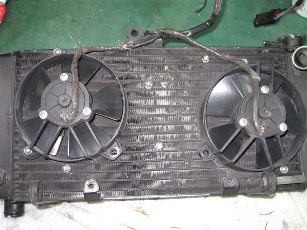 Then, because i was still having cooling issues in traffic I went with a cowl setup. I was going to have a custom Radiator made but the radiator guy said to cowl the stock one first. 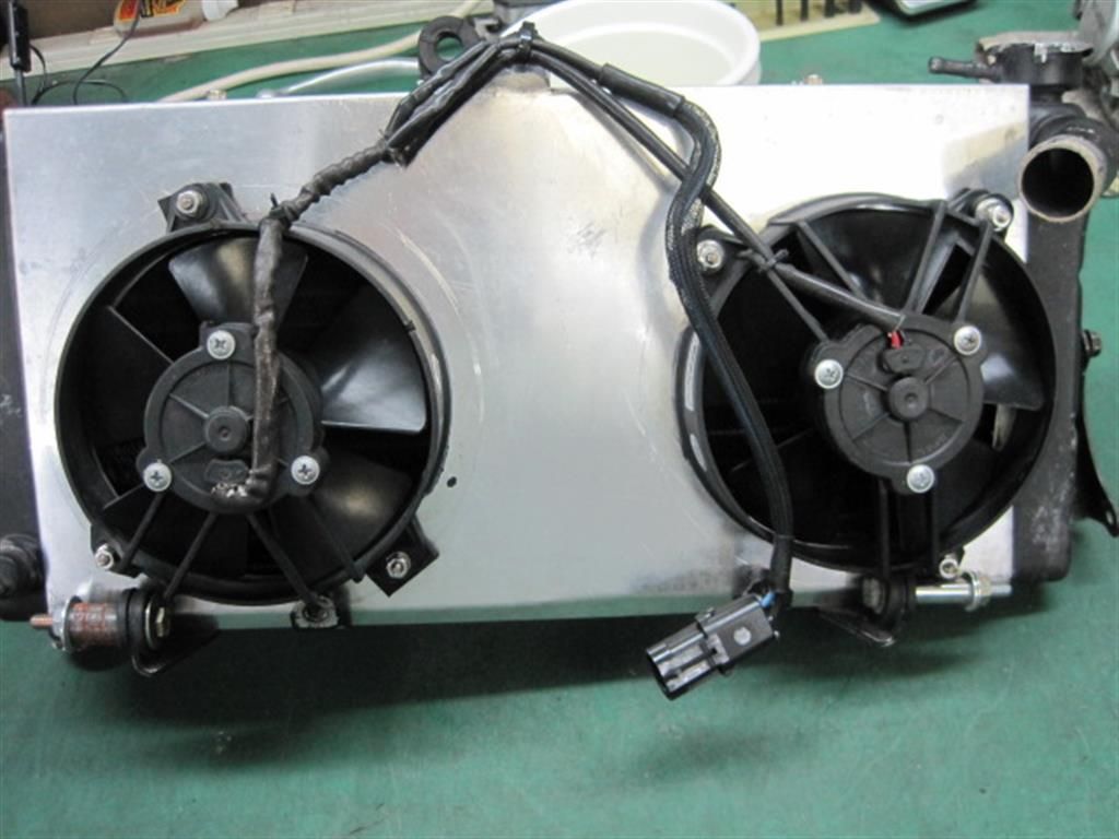 That was the solution for traffic overheating. But... I found out the hard way as I left for vacation that at speeds over 65 the bike would over heat. the custom radiator guy told me it was because there was air building up in the cowl at high speed, and recommended check valve type flaps to relieve the pressure buildup. 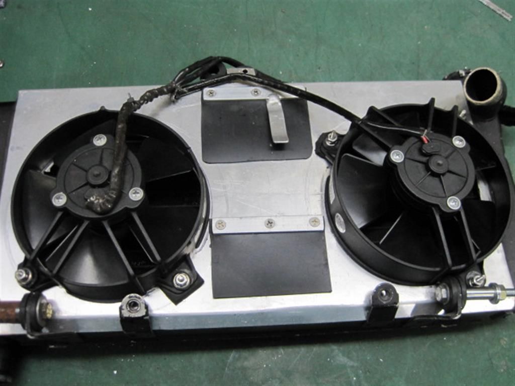
That has finally solved my cooling issues. Without the need for a new radiator. |
|
|
|
|
Logged
|
|
|
|
|
Anthony
|
|
« Reply #15 on: May 19, 2013, 01:42:08 PM » |
|
thanks Jeff K,
i'll start immediately with 2 fans, instead of 1, just to be safe.
what ambient temperatures do you usually have in your location?
here in Belgium a rare hot summer day is a 30°C, or 86°F.
1 more question :
how does the upper radiator mount look like ? i seem to miss that part. maybe some dimensions?
in the instructions it's described as 'smaller, and one of its holes is tapped'
Thanks in advance,
Anthony
|
|
|
|
|
Logged
|
|
|
|
|
Jeff K
|
|
« Reply #16 on: May 19, 2013, 01:51:45 PM » |
|
Its a small piece of aluminum flat bar. about 1/2 inch wide and 1 1/2 inches long. with one hole through' and one new tapped hole.
I live in Florida. 86 is a chilly day. ;-)
|
|
|
|
|
Logged
|
|
|
|
|
flsix
|
|
« Reply #17 on: May 19, 2013, 03:05:19 PM » |
|
Anthony, good luck with your project. Keep the pics coming so the rest of us can enjoy it vicariously through your work.
|
|
|
|
|
Logged
|
2013 F6B
ESCHEW OBFUSCATION
|
|
|
|
Anthony
|
|
« Reply #18 on: June 10, 2013, 09:09:13 AM » |
|
i have been too busy with the bike, now its time for an update on my progress: i continued to clean up the block : removed the ignition coils & the thermostat housing.  then i made a test setup, just to see if everything would line up : luckily i found out that the part between the carburator and the compressor would not line up correctly, and had been mounted backwards : Bill explained that this hole pattern was for the current model compressor, not the one i have. + the entrance was going from small to wider, instead of making a graduate entrance to the compressors entrance.  i corrected that, by milling slotted holes, and putting the connector on the other side of that alu plate.  while i had everything preliminary mounted, i found a nice place to move those 2 ignition coils, so that i could keep the existing spark plug cables : between the block and the manifold, on the left side. i made a stainless steel bracket to hang them on : this is a pic in progress  and here is the final, mounted result :  the manifold fits nicely over them, protecting them from the elements and sight. the only down side is that it makes it even more difficult to mount the compressor to the manifold, with those 4 bolts up. another very important step to be taken : cutting that 6" tube from the frame, where the OEM air filter is bolted on. am i really that crazy / desperate / sure i will not die a flaming death ??   apparently i am :  next step : before that manifold gets bolted on, it needs a bit more shine ! i brushed the rough surface on the bottom with a steel brush : (left side is done, right side is not )  the top side is a lot smoother, and easier to get to with a polish weel. left side original, right already pre-polished :  to finally come to this result :  i also turned a small thottle cable extention, so that i can still use standard lenght throttle cables. made in brass, a 9,0 mm diameter x 35 mm lenght body, with a M6 thread in it for 30 mm deep, and a 5,38mm nose for 12 mm long, slotted over the complete length with a 2,5 mm mill.  that's all for now, more pics & horror stories  to follow soon. Anthony |
|
|
|
|
Logged
|
|
|
|
|
flsix
|
|
« Reply #19 on: June 10, 2013, 09:29:23 AM » |
|
Anthony if you use a steel wire brush instead of stainless steel it can leave very small wire particles imbedded in the aluminum. These particles will rust when humidity and air hit them and leave small rust spots on your manifold. I hope with the final polishing process all those particles were removed,but if you see that happening you'll know why.
I worked in a fab shop for many years and about once a year someone would mistakenly grab the wrong brush for alum. work and have the rust specs show up.
Hope your good to go. I really like to see the work in progress. Thanks for posting the project.
|
|
|
|
|
Logged
|
2013 F6B
ESCHEW OBFUSCATION
|
|
|
|
Jeff K
|
|
« Reply #20 on: June 10, 2013, 03:15:02 PM » |
|
Anthony if you use a steel wire brush instead of stainless steel it can leave very small wire particles imbedded in the aluminum. These particles will rust when humidity and air hit them and leave small rust spots on your manifold. I hope with the final polishing process all those particles were removed,but if you see that happening you'll know why.
I worked in a fab shop for many years and about once a year someone would mistakenly grab the wrong brush for alum. work and have the rust specs show up.
Hope your good to go. I really like to see the work in progress. Thanks for posting the project.
I was thinking the same thing as i was reading that. Steel brush on aluminum will make rust. |
|
|
|
|
Logged
|
|
|
|
|
fantsybikr
|
|
« Reply #21 on: June 10, 2013, 06:21:15 PM » |
|
Great post..wtg..I am jealous 2..and yes keep the updates coming!
|
|
|
|
|
Logged
|
VRCCDS 0252
VRCC 26284
GWRRA 329832
|
|
|
|
Anthony
|
|
« Reply #22 on: June 11, 2013, 06:35:51 AM » |
|
Steel brush on aluminum will make rust.
$h!t, i will check that brush this evening, if its a plain steel or stainless brush.  fortunately i only touched the bottomside of the manifold with it, for the top i only used 3 different sissal wheels. i will keep an eye on it, and if necessary i will take it back off and polish again and again. i am getting more handy at this anyhow.  Anthony |
|
|
|
|
Logged
|
|
|
|
|
flsix
|
|
« Reply #23 on: June 11, 2013, 12:00:12 PM » |
|
Practice makes perfect. |
|
|
|
|
Logged
|
2013 F6B
ESCHEW OBFUSCATION
|
|
|
|
Anthony
|
|
« Reply #24 on: June 20, 2013, 08:10:39 AM » |
|
now that i found a new, easy way to upload a lot of high resolution pics, (dropbox : public folder) i can continue with this update : i know the manual says to just remove the thermostat housing bolts, to make sure it is correctly sealing of on the manifold, but i cut off the mounting tabs, so that it can move more free. (don't worry, i have a spare)  mounted back on the tubes it looks like this:  a new carter breather filter finally arrived at my dealer K&N 62-1360 with a 3/4" connection, plugs just right over that tube where the rubber hose used to be.  i dropped the 4 bolts to hold the compressor in the manifold, and put a strip of paper masking tape to hold them temporarily into place. dropped the O-rings (nr 124 = 31,4 mm x 2,6mm) in the grooves, and put a tiny strip of that masking tape to hold them there.  that way it was easy to put the manifold on the bike, only had to pull out the paper tape, and every O-ring was still in place. next step: putting the compressor onto the blower, with liquid sealant above & below the gasket. (sorry i forgot to take a pic there) by the way : that ignition coil plate is not making it easier to turn those bolts into the compressor... added a new micro V belt : et voila:  |
|
|
|
« Last Edit: June 20, 2013, 09:00:01 AM by Anthony »
|
Logged
|
|
|
|
|
Anthony
|
|
« Reply #25 on: June 20, 2013, 08:57:41 AM » |
|
detail on how the ignition coils are hidden below the manifold:  next step was to mount the carburator and air filter from Bill.   next was to put the radiator back, with the new ventilator. as i am still waiting for that 2nd fan to be delivered, and i really needed to be on the road, i started with just 1 fan. i had already seen pics of different model brackets, with bend instead of straight: i quickly learned that these allowed easier mounting of the fans on the radiator, i made me some new stainless steel brackets with bend, to mount the radiator. at the bottom side 1 tapped an M6, so that i can just turn the bolt in, without extra nut behind it.  and polished these up:  mounted the fan onto the radiator with tie raps, wired the thermostat to the negative, black fan wire,  mounted the radiator in place, added a bling bling spiral to the upper and lower hose, with a bling bling connection kit from valkyrieparts.de (a local sponsor)   it's starting to look better & better ! Anthony |
|
|
|
|
Logged
|
|
|
|
|
Anthony
|
|
« Reply #26 on: June 20, 2013, 09:15:08 AM » |
|
if more air goes in that engine, more air needs to get out as well. so now it was time to open that box i had already bought a year ago, a set of Carolina thunder exhausts, with bigger header pipes: inside dia = 30 mm instead of the 23 mm on Honda pipes.   put the engine hangers back in there  changed out my throtle cables for a stainless set,  and with my extension, it was very easy to mount and set them on the carb:  now i thought i was almost done, but boy was i in for a surprise ! anthony |
|
|
|
|
Logged
|
|
|
|
R J
Member
Posts: 13380
DS-0009 ...... # 173
Des Moines, IA
|
|
« Reply #27 on: June 20, 2013, 12:00:38 PM » |
|
Do you have those fans wire tied to the radiator fines?
If so, cause road bumps will shake the fan and then ya got a leak.
Don't bother asking how I know this.
Otherwise your installation looks good.
|
|
|
|
|
Logged
|
44 Harley ServiCar |
|
|
|
Jeff K
|
|
« Reply #28 on: June 20, 2013, 03:52:26 PM » |
|
A drip of super glue on two sides will keep the Orings in place while seating the manifold. A rubber band works great for holding the supercharger bolts up and out of the way, push the bolts up through and put a single band on top.
Those coils are going to get sofa king HOT. My keys get too hot to hold. The center of that motor take a lot of heat.
If you needed a fan you should have asked I have spares.
|
|
|
|
|
Logged
|
|
|
|
|
Jeff K
|
|
« Reply #29 on: June 20, 2013, 03:53:58 PM » |
|
And, the main source of install issues come from leaks between the supercharger and the manifold.
|
|
|
|
|
Logged
|
|
|
|
|
Anthony
|
|
« Reply #30 on: June 21, 2013, 06:37:19 AM » |
|
Do you have those fans wire tied to the radiator fines?
yes, that's what i understood the manual says to do. not just across the thin alu fins, but over one of those horizontal lines. what else did you guys do? build a holding frame for it, that is mounted on the tabs ? i still need to get back in there anyhow. Anthony |
|
|
|
|
Logged
|
|
|
|
|
Anthony
|
|
« Reply #31 on: June 21, 2013, 06:41:43 AM » |
|
If you needed a fan you should have asked I have spares.
i am actually still waiting, on 2 different car parts dealers, to deliver me a SPAL VA31-A101-46A or a similar VA37-A101-46A. over a month i am hearing " it will be here next week"... Anthony |
|
|
|
|
Logged
|
|
|
|
|
Oklahoma_Valk
|
|
« Reply #32 on: June 21, 2013, 01:51:04 PM » |
|
That is looking AWESOME. The coil mount job is super innovative, and original. However, I agree with Jeff K. Those babies are going to be HOT! Im not sure how that might affect the life of them.
I would think ANY and ALL innovations which could make the supercharged engine run COOLER would be time well spent. Also, I think your air filter is going to suck in a lot of hot air. If you could find a way to extend the air filter tube out toward the side of the bike, it would probably run better and make more power. BonS just about perfected this situation on his supercharged beauty.
Thanks for the awesome report! Keep it coming!
|
|
|
|
|
Logged
|
Let those who ride decide.  |
|
|
|
Anthony
|
|
« Reply #33 on: June 28, 2013, 05:37:35 AM » |
|
Do you have those fans wire tied to the radiator fines?
yes, that's what i understood the manual says to do. not just across the thin alu fins, but over one of those horizontal lines. what else did you guys do? build a holding frame for it, that is mounted on the tabs ? Anthony well i finally received that 2nd fan this week, so i can dig in there again.  what is the advised way to mount those fans on the radiator ? RJ, i don't want to ask how you know that tie raps are a bad idea, but i would love to know what is the better way the other thing i hope to do this weekend, is mount an airfilter and a fuel valve, because that Bill's new airfilter can not work with the OEM fuel valve. i already made a weekend trip to our local vrcc weekend, with the stock fuel valve and a nylon stocking from the lady of the house for a air filter, due to lack of other options & time. i have already purchased a compact high flow fuel valve. if that works i will continu with that and probably build my own air filter hose anyhow... Has anyone ever tried one of those chromed Harley styled air filter housings, with a hose to the outside of the left engine hanger ? Anthony |
|
|
|
|
Logged
|
|
|
|
|
BonS
|
|
« Reply #34 on: June 28, 2013, 06:51:03 AM » |
|
Something like this? I use a petcock that is accessible from the right side of the bike. The K&N air filter has an offset intake port and a sock pre-filter if desired. I slightly bias the air flow with Baker Air Wings to direct a cool air stream to it. The air filter metal stays cool to the touch so I'm sure the engine is getting cool dense air for best performance. I briefly looked at various Harley air filter back plates but the K&N was just too easy to install with a just a band clamp.  |
|
|
|
|
Logged
|
|
|
|
|
Fritz The Cat
|
|
« Reply #35 on: June 28, 2013, 08:01:52 AM » |
|
Wow, just wow.  |
|
|
|
|
Logged
|
|
|
|
|
Anthony
|
|
« Reply #36 on: June 30, 2013, 03:26:15 PM » |
|
I briefly looked at various Harley air filter back plates but the K&N was just too easy to install with a just a band clamp. Hey BonS, I had already seen a couple of pics of your setup and really like it. Can you send me pic from the right side, showing that tubing? If its that easy, i will bury the harley air filter idea. I looked up your earlier posts, and i understood you used 2,5" silicone tubing, first a 135° (?this one i can't picture me?), then a 90° turn. And a K&N Part nr RA067V. Thanks in advance, Anthony |
|
|
|
« Last Edit: June 30, 2013, 03:32:37 PM by Anthony »
|
Logged
|
|
|
|
|
BonS
|
|
« Reply #37 on: June 30, 2013, 05:07:43 PM » |
|
|
|
|
|
|
Logged
|
|
|
|
|
|
|
Anthony
|
|
« Reply #39 on: August 18, 2013, 04:04:00 PM » |
|
ok, time for an update: i have been riding a bit, wihout proper air filter, while waiting for parts and inspiration. only used a piece of a couple of the misses' stockings for every trip. i mounted a smaller fuel valve to make way for the air filter tubing. a high flow valve i found in a local Harley shop, i don't know the manufacturer:  i copied BonS air filter setup : i purchased 2 silicone tube elbows, and 2 aluminium tube connections, at Chargertech, a dutch company specialised in superchargers and affiliated parts. and a K&N air filter model RA067V. Unfortunately i had to find out that the 90° elbow i received has a sharper bend then the 135°. So i ordered another 90° to make the sharpes possible turns: i had to trim both alu connections, and cut down both elbows on both sides, to come to this:    this is how it looks mounted :   |
|
|
|
|
Logged
|
|
|
|
|