MarkT
Member

Posts: 5196
VRCC #437 "Form follows Function"
Colorado Front Range - elevation 2.005 km

|
 |
« on: June 20, 2015, 08:06:04 AM » |
|
Picked up a forward controls kit at the swap meet at Inzane. Installing it. Have a problem with brake authority. Have you installed this, and did you have the problem and fix it? First, I have to say if this was my product, it would not be ready for release. It's not even Beta-ready IMHO. I would make changes so it could be installed by anyone with just wrenches; not require a metal shop. And I would probably use a hydraulic rather than a mechanical linkage on the brake - though that would increase the cost but also the reliability and eliminate the problem I'm having, while making adjustment maintenance irrelevant. 1. The designers assumed the OEM return spring is adequate even with the extra friction of the more complex linkage. Not. The brake doesn't return to neutral and the light stays on. Added an appropriate spring around the plunger on the master cylinder: 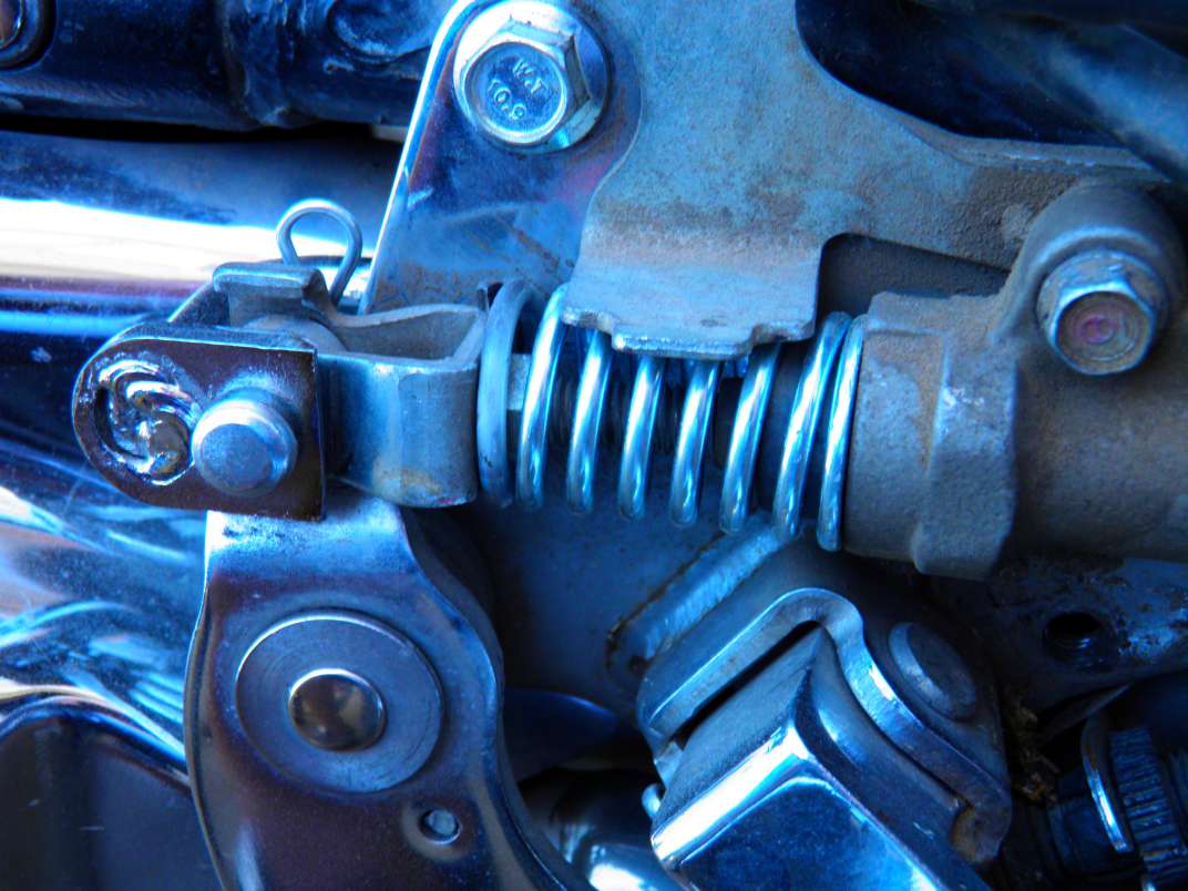 2. The pegs are too short for good access from the highway pegs. Granted, I didn't use THEIR highway pegs; don't even know if they supply them. They are not mentioned in the install sheet; weren't in the used kit. Could have been kept by the seller. I used my Kuryakyn pegs. Then made a 1" extender for both pegs in the kit - they are identical. Used a beefier bolt & nut. Haven't powder coated them yet. 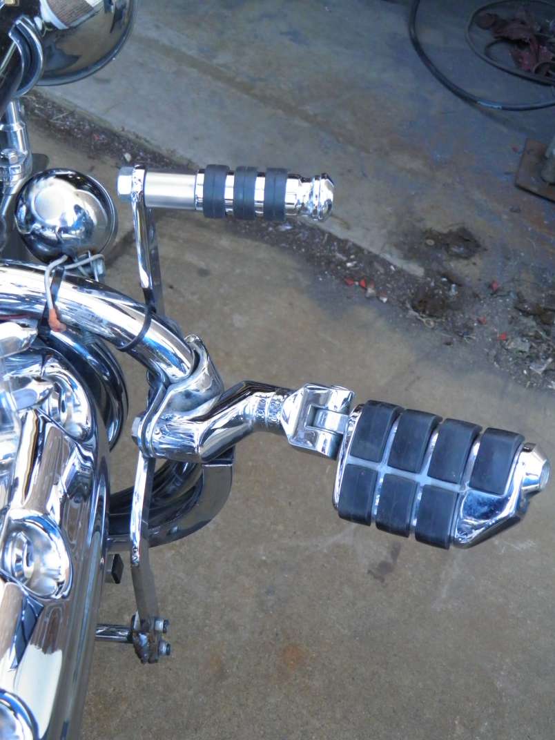 3. The adjustment bolts on the brake lever don't hold the setting against the force needed to brake. Should be much beefier and longer with a friction surface rather than slippery chromed. I just set it where needed and welded it. Not something that should need readjustment once it's finally set, since it operates a hydraulic master cylinder. Of course to adjust while installing, I have to grind off the weld and re-weld in the new position. 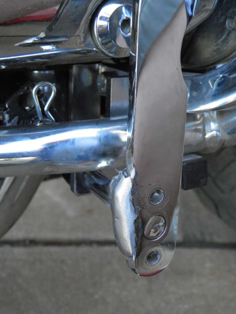 4. Now to the problem. There is no brake authority. I moved the fulcrum to increase the leverage - now the fwd brake has three times the leverage of the foot pedal - for 0.5 inch of movement of the OEM pedal, there's 1.5 inches at the fwd pedal. Still no authority. I welded an extension on the side of the crank plate to move the crank closer to the fulcrum - resulting in the 3-1 mechanical advantage over the footpedal. I did not install hyme joints as I was able to eliminate play with tight fittings on the ends of the rod - the linkage at the pedal is already tight. I had drilled and installed on oversized pin at the end of the master cylinder pushrod. Meanwhile observe the pull rod is not straight. I had to add another bend to it to move the crank closer to the fulcrum without hitting the crash crossbar. Even though it is 10mm in cross section, I am certain the only explanation here is flexing of the rod making the brake "spongy". Note the new crank position below the original hole, while the fulcrum is the round bar below the crash bar. The black is spray paint getting knocked off - it will eventually be powder coated. 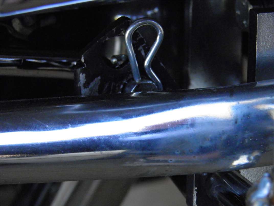 Note the pull rod is not straight so it flexes. 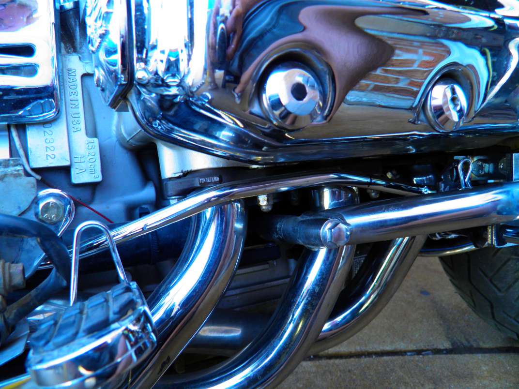 Note the rod goes behind the master cylinder. Also note the heavier pin at the terminus. 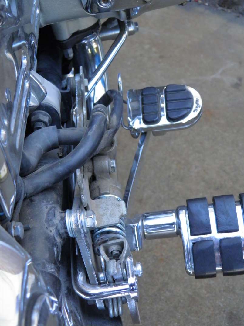 OK so my soln at this point is, I'm adding reinforcing to the pull rod to stop the flexing. 1/2" round steel rod, bent on the bender. and welded along the entire length of the pull rod, and fitted for clearance as needed. If this doesn't fix it, I'm at a loss. It's a bit of work to shape and fit it exactly, and weld along it's length, and powder coat once it works. Any engineers or others especially with experience on this problem - comments? |
|
|
|
« Last Edit: June 24, 2015, 03:08:32 PM by MarkT »
|
 Logged
|
|
|
|
hubcapsc
Member
Posts: 16816
upstate
South Carolina
|
|
« Reply #1 on: June 20, 2015, 10:30:15 AM » |
|
I've had mine most of the time I've had the bike. I think they work great. I remember when I was installing them I thought the brake action was bad. It went from bad to awesome just by me removing the OEM brake pedal from its pivot mount and cleaning/lubing it and putting it back together.  -Mike |
|
|
|
|
Logged
|
|
|
|
MarkT
Member
Posts: 5196
VRCC #437 "Form follows Function"
Colorado Front Range - elevation 2.005 km
|
|
« Reply #2 on: June 20, 2015, 04:37:12 PM » |
|
Thanks for the response. I wonder if you changed or realigned anything else with the R&R operation. Corrected some misalignment or something. My brake pedal has very little friction when operated sans the master cylinder & fwd linkage so doing your fix doesn't appear like it will help. I reinforced the rod, got the clearance squared away and it made no difference. Before I reinforced it, push hard slowly on the linkage and at a certain point the piston would just stop moving while the pedal continued fwd. But doing the same with the foot pedal, it would move the piston. Now I'm at a loss. Gonna sleep on it and start fresh tomorrow. Look for any and all friction points and possible reasons it's not delivering the force to the master cylinder. And force it with a hydraulic ram while measuring the linkage movement to find where it's stopping.
I'm wondering if this is the reason this kit was available at the swap meet. Didn't look very used. That wouldn't surprise me.
|
|
|
|
« Last Edit: June 20, 2015, 04:46:01 PM by MarkT »
|
Logged
|
|
|
|
|
DK
|
|
« Reply #3 on: June 21, 2015, 07:00:50 AM » |
|
I purchased & installed a set & removed it after a few days with the intention of making some improvements & re-installing.
My problems were:
1) The poorly designed "range of motion" adjustment mechanisms would not hold adjustment even after roughing the mating surfaces, smearing with loctite, and using 8 point bolts.
2) Too much "slop" in the drill-hole & pin linkages.
3) As Mark T notes, there is too much flex and range of motion disparity in the brake linkage rod. Also,
the attachment to the master cylinder is poorly designed.
My loosely thought out plan for straightening out this mess involves:
1) Replacing all linkage pivots with heim joints and incorporating threaded rod adjustable linkage rods with the heim joints. Probably will use stainless all thread covered by chromed tubing for ridgity and appearance.
2) Welding range of motion adjustment mechanisms in fixed position after determining approximate initial setting as per Mark T and doing subsequent adjustment by threaded rod & heim joint.
3) I have purchased a brake pedal from eBay for $20.00. I'm going to weld a crank arm below it's pivot point and connect it directly to the crank arm of the forward control brake pedal with threaded rod & heim joints.
4) I like Mark's inclusion of a spring return for the brake pedal. I don't know whether I will do it with a compression spring at the MC as he did or with a contraction spring working against the crank arm.
5) I've purchased from eBay, also for $20.00, a complete shifter pedal assembly. (It includes the short arm attached to the shifter shaft next to the case). I'm going to weld a crank arm to the short arm so as to allow attaching a heim joint and adjustment rod connecting directly to the crank arm of the forward brake pedal.
I'm mainly doing this so as not to interfere with the operation of my "rattle bar" shifter which I love, but also because it will be easier to adjust and I don't like the klutzy look of the original design.
The controls as shipped simply do not work well. With improvement I think they will be a great addition to the Valk.
Dan
Dan
|
|
|
|
|
Logged
|
Machinery has a mysterious soul and a mind of its own.
|
|
|
MarkT
Member
Posts: 5196
VRCC #437 "Form follows Function"
Colorado Front Range - elevation 2.005 km
|
|
« Reply #4 on: June 21, 2015, 05:16:08 PM » |
|
Thanks Dan. I agree with all you said and am going to look into your ideas, I think that's a better plan. Don't know if I will go as far as using threaded rod and heim joints. That might be a winter project. Want to get it working now. I have continued with putzing with it. After making the pull rod much more rigid and having increased it's leverage as compared to the OEM pedal to 3X the force, it works better but still not good enough. I'm thinking I might do as you said - make a direct linkage to a crank at the OEM brake pedal arm. Meanwhile with more use and adjustment, the shifter cannot be adjusted to not run out of movement on one end of it's travel or the other. It might work on a new bike with unworn linkage, but it doesn't work on mine. I'm going to increase the travel ratio by lengthening the crank arm and adjusting the other parts as needed. I believe if this is done right, as you said it will be a very nice mod. I already like doing full lock turns at higher speed; U-turns feel much more balanced and I can be way faster doing Jerry Paladino exercises with my feet up high on the highway pegs, while I hear the footpegs dragging of course I don't feel it with my feet up. I don't know why the bike just feels more balanced while being aggressive, but I'm glad it does. BTW if you want to install a spring as I did, the correct spring is P/N C-832 at www.centuryspring.com I picked it up at True Value hardware and cut off four coils, and heated & bent the end and sanded it to give it a 90° end. |
|
|
|
« Last Edit: June 21, 2015, 05:39:57 PM by MarkT »
|
Logged
|
|
|
|
|
DK
|
|
« Reply #5 on: June 22, 2015, 07:11:23 AM » |
|
Mark, If you will recall, we discussed this briefly as we were departing from InZane - we talked about the "shifter pivot" search string. Since returning from InZane, there has been a new post describing how to make your own pivot: http://www.valkyrieforum.com/bbs/index.php/topic,74563.40.htmlIt's a simple straight forward mod which will definitely solve the wandering adjustment problem of the shifter mechanism. Also, using the above search string or my posting history, you will se my suggestion for a simple mod of the existing pivot being marketed for the GW. Also, the GW pivot vendor is working on modifying his pivot for the Valk. You might call him & check the status. Dan |
|
|
|
|
Logged
|
Machinery has a mysterious soul and a mind of its own.
|
|
|
MarkT
Member
Posts: 5196
VRCC #437 "Form follows Function"
Colorado Front Range - elevation 2.005 km
|
|
« Reply #6 on: June 22, 2015, 08:16:40 AM » |
|
Thanks for the link. Looking at his design and it's function, looks to me like I can replicate his function with fewer parts and less effort. I'd just buy his if it was in production but there's no word on that so it appears like it's not available for an unknown time. Bringing a product to the market is much more involved than just developing the prototype, so time could be long. I want to get this project done now. My shifter with it's poor design and 116k wear is too sloppy to work with the BBT forward shifter linkage. I was surprised when I saw the kludgy design, just to make the shifter shaft detour around the exhaust. Add to that the kludgy BBT design and it's a wonder they thought it would ever work - or if it did, how long it would work before failure.
Well I have a delay in my availability to work on this coming up, so I'll see if I can get the brake linkage to where it's at least working with sufficient brake authority, and having proved the concept, make it look nice with heim joints, adjustability and chrome later. Right now, the shifter works sort of but it's unreliable, sometimes doesn't downshift and never upshifts from 1-2 but goes from 1-N and have to use the OEM lever to get to 2. Don't know what BBT was thinking - I wouldn't want my name on this product. The brake is pretty much worthless.
|
|
|
|
« Last Edit: June 22, 2015, 08:24:47 AM by MarkT »
|
Logged
|
|
|
|
hubcapsc
Member
Posts: 16816
upstate
South Carolina
|
|
« Reply #7 on: June 22, 2015, 08:21:03 AM » |
|
or if it did, how long it would work before failure.70,000+ trouble free miles so far for me  -Mike
|
|
|
|
|
Logged
|
|
|
|
MarkT
Member
Posts: 5196
VRCC #437 "Form follows Function"
Colorado Front Range - elevation 2.005 km
|
|
« Reply #8 on: June 22, 2015, 08:32:39 AM » |
|
or if it did, how long it would work before failure.70,000+ trouble free miles so far for me -Mike Take a close look at the overall shifter shaft with the addition of the BBT bolt-on lever. It looks like they hardly considered the sloppy design they were adding to - considering the actual axis of rotation and their added force of leverage; how the side vectors would accelerate wear and cause failure - worn bushings, leaking seals, additional slop and so on. Apparently it only works for SOME installs, depending on individual idiosyncrasies and wear. Neither side works on mine after extensive adjustment and even modding the unit. Yeah maybe I have high standards but I don't admire sloppy engineering or execution and require reliability so I don't get to tell the Harley on-the-road-breakdown stories. I'd say Dan and most of us have similar standards. Why we ride Hondas not Harleys, and why the design of both the BBT product and Honda's OEM shifter linkage is an aberration in our paradigm. BAD DESIGN. |
|
|
|
« Last Edit: June 22, 2015, 08:37:37 AM by MarkT »
|
Logged
|
|
|
|
|
DK
|
|
« Reply #9 on: June 22, 2015, 09:04:46 AM » |
|
All it basically requires to use the GW pivot on the Valk is to remove the width of the pivot bracket from the long pipe spacer used in the rear attachment point of the crashbar and insert the hanger bracket as an additional spacer.
If I'm wrong about this and the Valk & GW engine housings are different, it would only require welding an appropriately located attachment ear to the long spacer & attaching the pivot hanger bracket to it.
Dan
|
|
|
|
|
Logged
|
Machinery has a mysterious soul and a mind of its own.
|
|
|
MarkT
Member
Posts: 5196
VRCC #437 "Form follows Function"
Colorado Front Range - elevation 2.005 km
|
|
« Reply #10 on: June 22, 2015, 10:24:03 AM » |
|
It's worse now. The shifter upshifts only, but not from 1-2, doesn't downshift and now impedes the OEM shifter from downshifting. After pressing the downshift, it will go down one gear but then doesn't reset so the fwd shifter doesn't work and neither does the OEM. Too much friction in the linkage for the internal OEM reset spring to overcome. I had to start off from a stop in 3rd gear in traffic.
I rode to True Value and picked up some Heim joints and other parts to fix the brake. After I get that done I'll work on the shifter.
|
|
|
|
|
Logged
|
|
|
|
|
DK
|
|
« Reply #11 on: June 22, 2015, 07:49:11 PM » |
|
That was pretty much my experience.
|
|
|
|
|
Logged
|
Machinery has a mysterious soul and a mind of its own.
|
|
|
MarkT
Member
Posts: 5196
VRCC #437 "Form follows Function"
Colorado Front Range - elevation 2.005 km
|
|
« Reply #12 on: June 23, 2015, 02:39:44 PM » |
|
Just finished replacing the rod linkage on the brake side with a straight hollow rod with left and right hand 7/16X20 nuts welded on it, welded a bellcrank on the brake OEM brake lever and 7/16 male heim joints on both ends of the tube. Put the left hand one in front, a long nut on the back for wrenching it and will put a jam nut there too if it moves. Took it for a spin. NOW I have some BRAKES! Excellent brake authority - even better than the OEM pedal. Very easy adjustment, too. I'll take some pics and measurements and post later. Took a couple experiments to get the parts to fit and get the leverage ratio right. Haven't "prettified" it yet. Might just powder coat the parts black as that's expedient. Maybe chrome later. I was tickled that my local True Value had Heim joints - quite a selection in fact. Maybe because this is ranching country.
Now attacking the shifter side. Eventually I want to address the kludgy linkage Honda put on there, like on the site DK pointed to. Maybe later. Just want to get it fixed for now.
|
|
|
|
« Last Edit: June 23, 2015, 03:24:29 PM by MarkT »
|
Logged
|
|
|
|
MarkT
Member
Posts: 5196
VRCC #437 "Form follows Function"
Colorado Front Range - elevation 2.005 km
|
|
« Reply #13 on: June 23, 2015, 05:26:07 PM » |
|
Here's a couple shots. The rear crank arm pivot is 2.3" above the center of the OEM brake arm pivot on center. The heavy welding is on the back, out of sight. I moved the original hole on the BBT arm in front down just enough so the Heim joint won't hit the cylinder head (filled in the hole with weld, ground smooth then redrilled it for just enough clearance). Set the arm angle about 10° back from parallel with the lever arm up to the peg and welded it there. (Didn't measure it and now it's hard to see behind the crash bar. But you need to be careful not to run out of travel hitting the front of the fixture. This position will allow sufficient clearance for the hollow tube, which is 0.75OD.) Length of the pull bar as needed to put the threaded nuts welded on the ends, in the center of the travel on the Heim joint mount threads. Again, and obviously, you need a left hand and a right hand Heim joint (and the nut it screws into) so you can adjust the length by just turning the center, like a turnbuckle. The hollow tube gives the screw on the Heim joint a place to retract into. 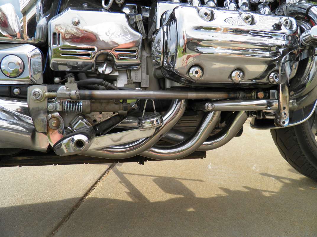 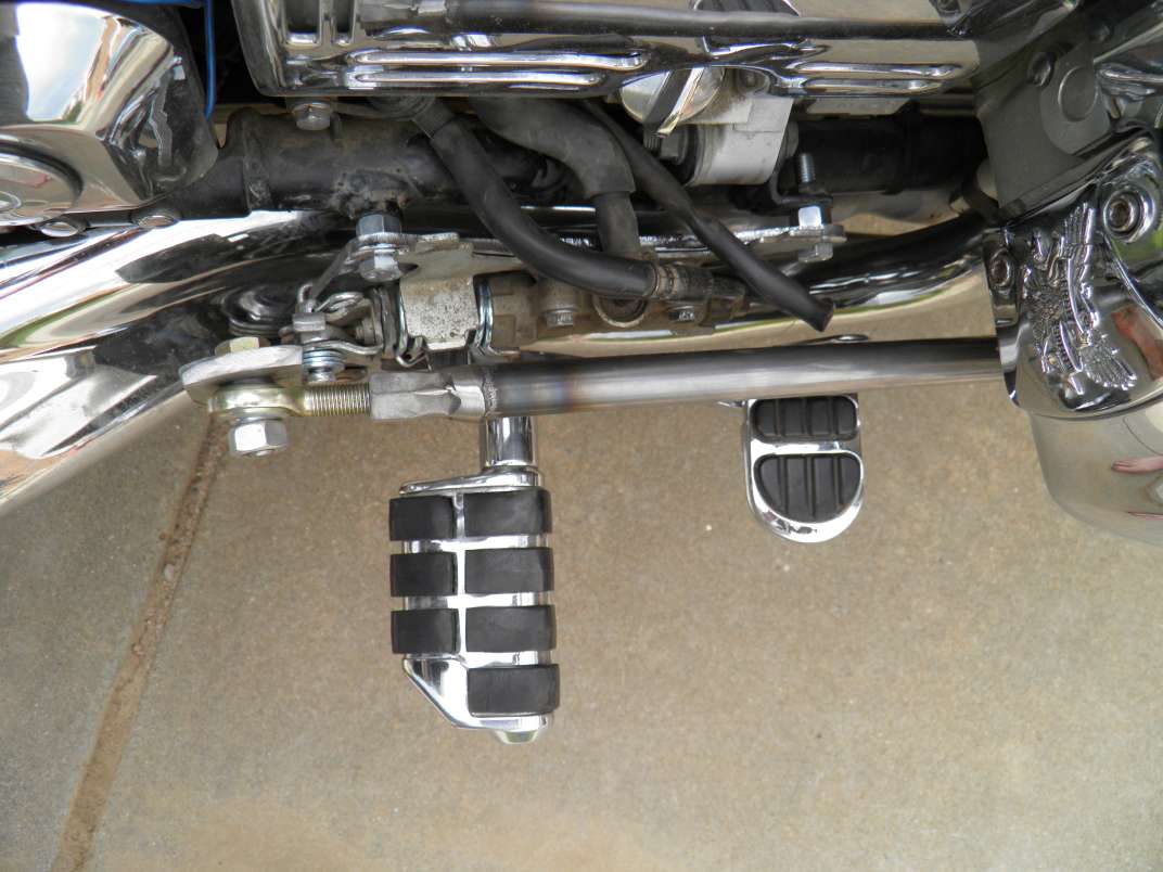 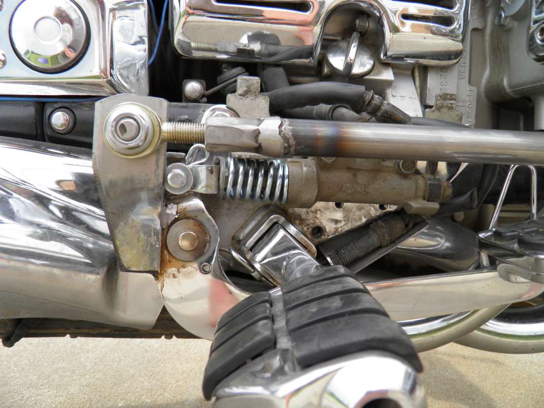 |
|
|
|
« Last Edit: June 23, 2015, 05:50:21 PM by MarkT »
|
Logged
|
|
|
|
|
DK
|
|
« Reply #14 on: June 23, 2015, 06:14:49 PM » |
|
Looks good.
Dan
|
|
|
|
|
Logged
|
Machinery has a mysterious soul and a mind of its own.
|
|
|
MarkT
Member
Posts: 5196
VRCC #437 "Form follows Function"
Colorado Front Range - elevation 2.005 km
|
|
« Reply #15 on: June 24, 2015, 11:17:46 AM » |
|
Looking at the mod developed by Fisch in Bavaria - http://www.valkyrieforum.com/bbs/index.php/topic,74563.40.html - he did a fine job, while of course he's looking at producing a bolt-on product for sale. Not known when if ever it will be ready to buy, and I need a soln soon. So with my metal shop, I can take his idea of adding a pivot support on the end of the shaft, with the same axis as the shaft at the casing, and simplify it a lot. Don't need his parts A & B, or cut up an OEM shifter shaft. Just the Heim joint, part H in his diagram, sundry bolts & nuts and can put it together with welding and a couple pieces of scrap metal to connect from the Heim joint to the shaft. If I weld the heim joint, fixed to the shaft instead of attaching it to the shifter arm I will be able to move the shifter position on the end of the splined shaft at will. This would also be compatible with existing BBT fwd controls linkage. On which I might add Heim joints at pivot points anyway if there is still slop to address after this mod. I'm tied up for the next couple of weeks, before I can return to this project. |
|
|
|
« Last Edit: June 24, 2015, 11:19:44 AM by MarkT »
|
Logged
|
|
|
|
|
RUDE DOG - Steelers
|
|
« Reply #16 on: June 25, 2015, 08:09:32 PM » |
|
I bought these awhile back because it was the only option for Forward Controls. I didnt like much about the setup. Boxy looking hardware, nothing lined up good, rear brake was useless and the worst for me was the reverse shift pattern.
Mark T, make a set worth using and I'll buy it.
|
|
|
|
|
Logged
|
|
|
|
hubcapsc
Member
Posts: 16816
upstate
South Carolina
|
|
« Reply #17 on: June 26, 2015, 04:31:42 AM » |
|
the reverse shift pattern.? ? ? I'm glad I got one of the good sets -Mike
|
|
|
|
|
Logged
|
|
|
|
|
DK
|
|
« Reply #18 on: July 02, 2015, 06:31:26 AM » |
|
Looking at the mod developed by Fisch in Bavaria - http://www.valkyrieforum.com/bbs/index.php/topic,74563.40.html - he did a fine job, while of course he's looking at producing a bolt-on product for sale. Not known when if ever it will be ready to buy, and I need a soln soon. So with my metal shop, I can take his idea of adding a pivot support on the end of the shaft, with the same axis as the shaft at the casing, and simplify it a lot. Don't need his parts A & B, or cut up an OEM shifter shaft. Just the Heim joint, part H in his diagram, sundry bolts & nuts and can put it together with welding and a couple pieces of scrap metal to connect from the Heim joint to the shaft. If I weld the heim joint, fixed to the shaft instead of attaching it to the shifter arm I will be able to move the shifter position on the end of the splined shaft at will. This would also be compatible with existing BBT fwd controls linkage. On which I might add Heim joints at pivot points anyway if there is still slop to address after this mod. I'm tied up for the next couple of weeks, before I can return to this project. Mark, Where & how do you propose to connect the Heim joint to a fixed point on the engine? Dan |
|
|
|
|
Logged
|
Machinery has a mysterious soul and a mind of its own.
|
|
|
MarkT
Member
Posts: 5196
VRCC #437 "Form follows Function"
Colorado Front Range - elevation 2.005 km
|
|
« Reply #19 on: July 02, 2015, 08:56:00 PM » |
|
Looking at the mod developed by Fisch in Bavaria - http://www.valkyrieforum.com/bbs/index.php/topic,74563.40.html - he did a fine job, while of course he's looking at producing a bolt-on product for sale. Not known when if ever it will be ready to buy, and I need a soln soon. So with my metal shop, I can take his idea of adding a pivot support on the end of the shaft, with the same axis as the shaft at the casing, and simplify it a lot. Don't need his parts A & B, or cut up an OEM shifter shaft. Just the Heim joint, part H in his diagram, sundry bolts & nuts and can put it together with welding and a couple pieces of scrap metal to connect from the Heim joint to the shaft. If I weld the heim joint, fixed to the shaft instead of attaching it to the shifter arm I will be able to move the shifter position on the end of the splined shaft at will. This would also be compatible with existing BBT fwd controls linkage. On which I might add Heim joints at pivot points anyway if there is still slop to address after this mod. I'm tied up for the next couple of weeks, before I can return to this project. Mark, Where & how do you propose to connect the Heim joint to a fixed point on the engine? Dan I expect to put it near the end of the crashbar mount bolt head, coaxially with the shifter shaft that comes out of the casing, and weld it to a collar that extends towards the engine alongside the shifter shaft, then welds to the shifter shaft. I'm not working on it right now, have something else going on. |
|
|
|
|
Logged
|
|
|
|
|
DK
|
|
« Reply #20 on: July 03, 2015, 09:35:56 AM » |
|
I'm going to try to incorporate a coupling nut welded to the long spacer between the crashbar and the engine or to the shifter shaft.
I think it will be convenient to have some means to adjust the arc of the pivot so as to ensure that its travel is concentric with the movement of the shifter arm.
Let's compare notes when you get back on this.
Dan
|
|
|
|
|
Logged
|
Machinery has a mysterious soul and a mind of its own.
|
|
|
|